
2
Safety notes
Installation/assembly
Operating Instructions – MOVIGEAR
®
classic
10
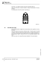
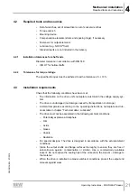
If necessary, use suitable, sufficiently dimensioned handling equipment.
Observe the information on climatic conditions in chapter "Technical data" of the docu-
mentation.
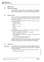
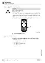
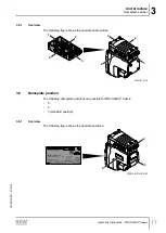
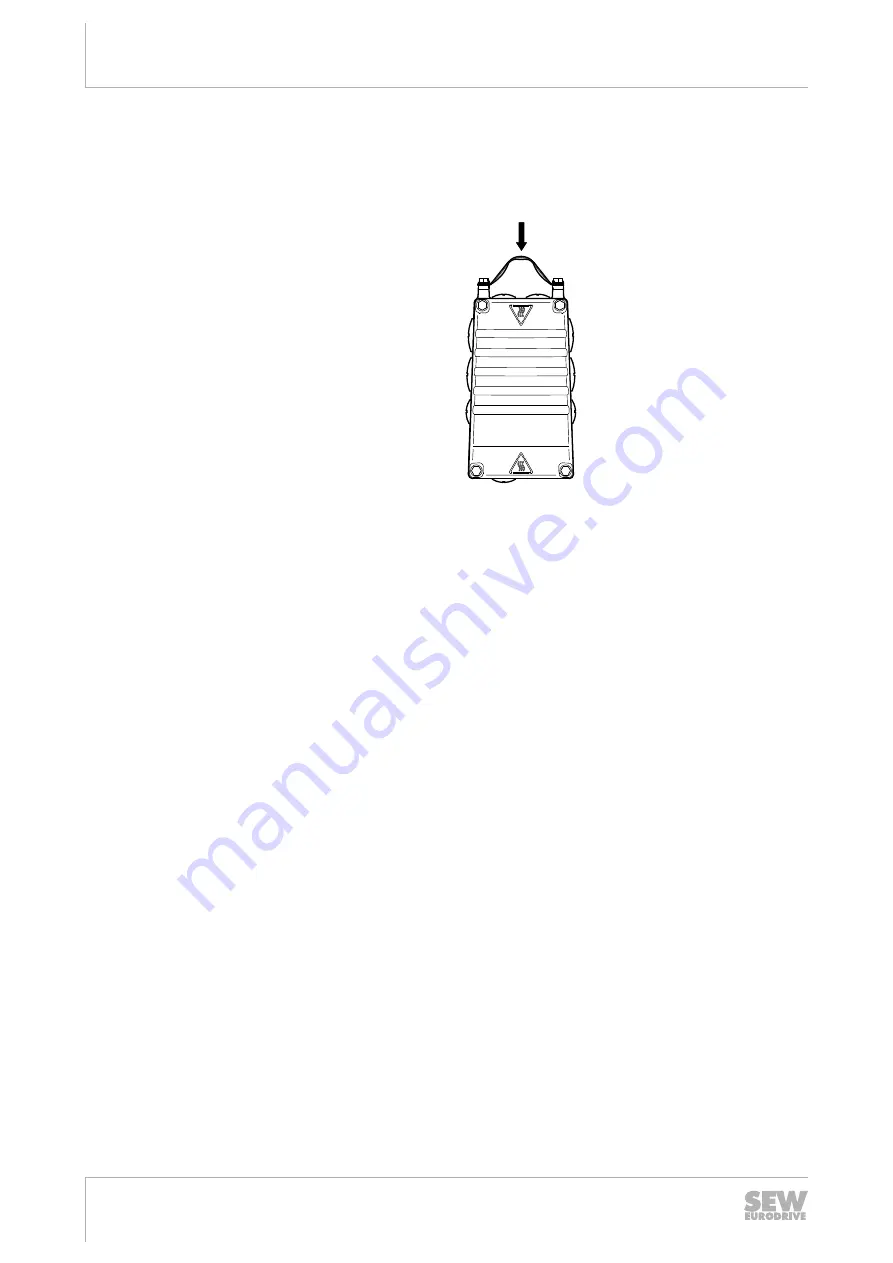
The following figure shows the position of the lifting eye.
PE
W
V
U
X4
X2
+
-
KTY
28228871
21488241163
2.6
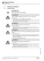
Installation/assembly
Ensure that the product is installed and cooled according to the regulations in the doc-
umentation.
Protect the product from excessive mechanical strain. The product and its mounted
components must not protrude into the path of persons or vehicles. Ensure that com-
ponents are not deformed and that insulation spaces are maintained, particularly dur-
ing transportation. Electric components must not be mechanically damaged or des-
troyed.
Observe the notes in the chapter "Mechanical installation" of the documentation.
25805134/EN – 07/2018