


16
Operating Instructions – Safety-Related BST Brake Module
4
Requirements on external safety controller
Safety-Relevant Conditions
4.3
Requirements on external safety controller
A safety relay can be used as an alternative to a safety controller. The following require-
ments apply analogously.
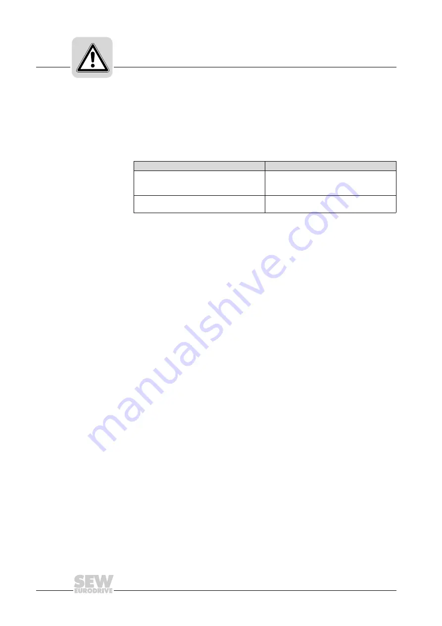
• The safety controller and all other safety-related subsystems must be approved for
at least that safety class which is required in the overall system for the application-
related safety function. The following table shows an example of the required safety
class of the safety controller.
• The wiring of the safety controller must be suitable for the required safety class, (see
manufacturer documentation). The safety-related control voltage V
24 V safe
can be
safely disconnected either at the positive, or the positive and negative pole. SEW-
EURODRIVE recommends bipolar disconnection.
• The values specified for the safety controller must be strictly adhered to when
designing the circuit.
• The switching capacity of the safety relays or the relay outputs of the safety controller
must correspond at least to the maximally permitted, limited output current of the
safety-relevant control voltage V
24 V safe
.
Observe the manufacturer's instructions
concerning the permitted contact loads and fusing that my be required for the
safety contacts. If there are no manufacturer's instructions for fusing, the
contacts must be protected with 0.6 times the nominal value of the maximum
contact rating specified by the manufacturer
.
• To ensure protection against unintended restart in accordance with EN 1037, the
safety controllers must be designed and connected in such a way that resetting the
control device alone does not lead to a restart. A restart may only be carried out after
a manual reset of the safety circuit.
• The input of the safety-relevant control voltage V
24 V safe
of the safety-relevant BST
brake module (terminal 5/6) is equipped with a serial polarity protection diode and a
buffer capacitor with C = 6
μ
F. This must be considered as load when dimensioning
the switching output.
• When switching off the BST with tested safe outputs, the switch-off test pulses must
not exceed 1 ms. The next pulse blanking cannot reoccur earlier than after 20 ms.
Application
Safety controller requirements
Category 3 according to EN 954-1
Category 3 according to EN 954-1
Performance level d according to EN ISO 13849-1
SIL 2 according to EN 61508
Performance level d according to EN ISO 13849-1
Performance level d according to EN ISO 13849-1
SIL 2 according to EN 61508
Buy: www.ValinOnline.com | Phone 844-385-3099 | Email: [email protected]


