SEON Trooper TR4 Скачать руководство пользователя страница 41

Configuring the DVR

700-0035 R004

3–7

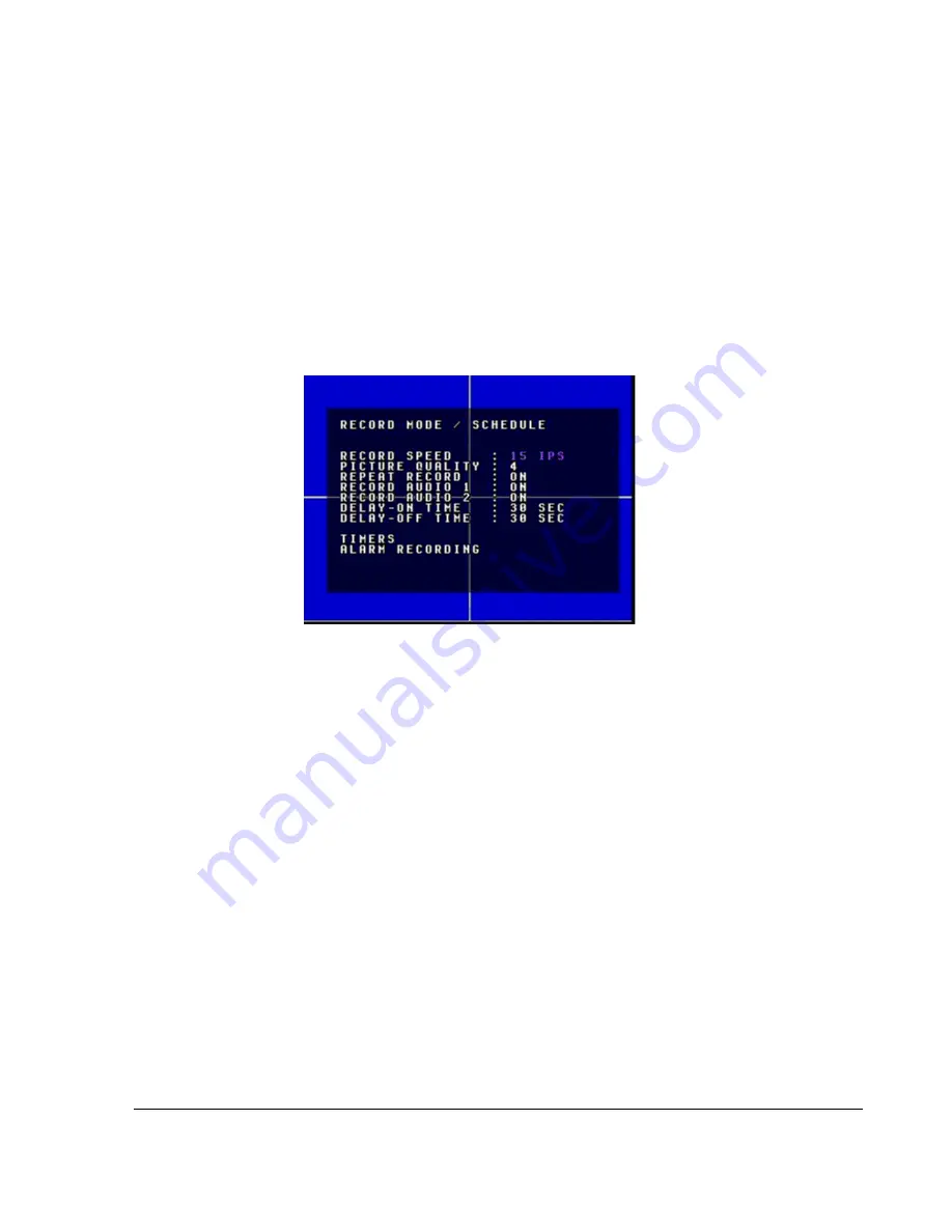
3.2.4. Using the Record Mode/Schedule Menu

Use the Record/Schedule menu to set the camera speed in images per second (

IPS

), 

the picture quality, the Delay-On and Delay-Off times, and other general 
recording options.

To view the Record Mode/Schedule menu:

1. On the main menu, press the 

CH

3/Up arrow or 

CH

4/Down arrow button to 

highlight Record Mode/Schedule.

2. Press the 

ENTER

 button.

The Record Mode/Schedule menu appears as shown in Figure 3-5.

\

To change a setting on the sub-menu:

1. Press the 

CH

3/Up arrow or 

CH

4/Down arrow button to highlight the setting 

you want to change.

2. Press the 

CH

1/Left or 

CH

2/Right arrow button to change the value. Or turn the 

JOG

 wheel clockwise or counterclockwise to change the value.

3. To exit the menu, press the 

MENU

 button.

4. Repeat these steps to set the Record Speed, Picture Quality, Repeat Record, 

Record Audio 1 and 2, Delay-On Time, Delay-Off Time, Timers, and Alarm 
Recording. See Table 3-4.

Figure 3-5

Record Mode/Schedule menu

Содержание Trooper TR4

Страница 1: ...700 0035 Document part number 700 0035 R004 Trooper TR4 Plus Mobile Digital Video Recording DVR System Manual Type Installation and User s Guide...

Страница 2: ......

Страница 3: ...RIBED HEREIN INCLUDING WITHOUT LIMITATION ANY DESCRIPTION OF GOODS OR SERVICES SPECIFICATIONS MODELS DRAWINGS OR DIAGRAMS b DOES NOT ASSUME AND SHALL NOT BE SUBJECT TO AND DISCLAIMS ANY AND ALL RESPON...

Страница 4: ......

Страница 5: ...tallation and User s Guide for the Trooper Plus G Mobile DVR Conventions Used Abbreviations and Acronyms CAUTION Cautions identify conditions or practices that could result in damage to the unit or to...

Страница 6: ...Design Inc as well as its products and services by visiting www seon com SA Series Wedge Camera Setup Guide Document part number 700 0004 SJ Series Dome Camera Setup Guide Document part number 700 00...

Страница 7: ...Cable Connections 2 6 2 5 Step 4 Connecting the Power and Ignition Harness Fuses and Fuse Holders 2 8 2 6 Step 5 Connecting the Alarm Input Harness and Alarm Switch 2 10 2 7 Step 6 Connecting the Sig...

Страница 8: ...Alarm Buzzer to OFF ON 4 10 4 7 Replacing the Hard Drive 4 10 4 7 1 Removing the Hard Drive 4 10 4 7 2 Installing the Hard Drive 4 11 4 8 Downloading Video to a Personal Computer 4 11 4 9 Voltage Disp...

Страница 9: ...chedule menu 3 7 Figure 3 6 Timers menu 3 10 Figure 3 7 Alarm Recording configuration menu 3 12 Figure 3 8 Signals menu 3 16 Figure 3 9 Calibrate Speed menu 3 17 Figure 3 10 Calibration in progress me...

Страница 10: ...vi...

Страница 11: ...ble 3 7 Picture quality settings 3 13 Table 3 8 Estimated recording time in hours with 40 GB hard drive 3 14 Table 3 9 Estimated recording times in hours with 80 GB hard drive 3 14 Table 3 10 Estimate...

Страница 12: ...viii...

Страница 13: ...CHAPTER 1 Introduction This chapter describes the product features and components of the Trooper TR4 Plus Mobile Digital Video Recording DVR System TR4 Plus System...

Страница 14: ...recorder M JPEG compression Four video channel and two audio channels Replaceable upgradeable hard drives to extend recording times Downloadable images and video using CompactFlash cards On screen dis...

Страница 15: ...menu system or play back short video clips If the vehicle ignition is turned ON pressing the button for 5 seconds during the Delay On interval will power up the DVR and start recording If the vehicle...

Страница 16: ...alarm 9 DVR Buttons See Table 1 2 10 Hard Drive Access indicator yellow Illuminates when the DVR is accessing the hard drive 11 Hard Drive Power indicator green Illuminates when the hard drive has be...

Страница 17: ...ode press the CH1 button to change which camera is in large image and which is the small PIP image In quad mode press any of the camera channel buttons to see that image full screen ZOOM NEXT P Pressi...

Страница 18: ...Y Pressing the COPY button provides a menu for backing up information to a CompactFlash card See Using the COPY Button on page 4 8 DISPLAY Pressing the DISPLAY button provides on screen information su...

Страница 19: ...nals input connector 6 pin 5 used 7 LAN Ethernet LAN connector 8 VIDEO OUT Video output jack Yellow RCA style 9 AUDIO IN 1 2 AUDIO OUT 1 2 Audio input jacks White RCA style Audio output jacks Red RCA...

Страница 20: ...system that allows for easy DVR installation and exchange A slotted cable entry that allows connectors to be inserted into the lock box after installation Mounting patterns that can accommodate a hor...

Страница 21: ...CHAPTER 2 Installation This chapter provides information and procedures for installing the TR4 Plus System...

Страница 22: ...placed inside the box for shipping such as the camera and the harnesses Assemble the necessary tools for installation Materials required You will need these materials to complete the TR4 Plus DVR ins...

Страница 23: ...emove it from the lock box 2 Slide the DVR out of the lock box by pulling on the two bracket tabs at the front of the DVR 3 Detach the lid from the lock box by removing the two retaining screws on eit...

Страница 24: ...he right side If necessary swap the cable grommet and the hole plug 5 Use 3 of the enclosed 10 sheet metal screws or the 10 1 self drilling screws to attach the lock box to the floor See Figure 2 2 6...

Страница 25: ...R slides in 2 3 1 Connecting to the DVR Back Panel Figure 2 3 shows the back panel of the TR4 Plus DVR which provides the connectors for the cameras power input harness alarm input harness video in an...

Страница 26: ...e Camera Cable Connections 2 4 1 Checking the Camera Cable Connections The TR4 Plus System uses an integrated mini DIN connector for the camera signal The cable comes prewired into the camera but in t...

Страница 27: ...panels Pulling from the wire end will require the cable to be disconnected from the camera Feed the cable through the large cable grommet on the DVR lock box The connectors can be fed through the gro...

Страница 28: ...ck negative battery power wire to the battery s negative terminal If there is a master battery switch in the battery compartment connected to the battery s negative terminal connect the black negative...

Страница 29: ...er wires to points as close to the battery as possible Never connect the ground wire black wire to the vehicle chassis by drilling a hole into a panel and using a sheet metal screw The ground connecti...

Страница 30: ...1 Connect the red and black wires from the alarm input harness together to activate the alarm input OR Connect the red wire to electrical ground to activate the alarm input 2 Connect the alarm input c...

Страница 31: ...GH or 0 VDC Active LOW See Using the Signals Speed GPS Menu on page 3 16 The wire colors for wiring to the indicators and default text are described in Table 2 3 The indicators can be connected to any...

Страница 32: ...trol Module TCM The TR4 Plus DVR is able to interface directly to some types of TCM in vehicles Contact Seon Design for more information about interfacing to different TCMs To connect the speed signal...

Страница 33: ...t is properly installed Check that all connections are tight System Install the fuses Plug the video monitor into the DVR Power up the system Confirm that all the camera and audio sources are operatin...

Страница 34: ...2 14...

Страница 35: ...CHAPTER 3 Configuring the DVR This chapter provides information and procedures for configuring the DVR...

Страница 36: ...provided in a small screen for disk size DISK operating status OPER record position R POS and recording speed SPEED Press the DISPLAY button several times to choose the desired on screen information...

Страница 37: ...tely 20 seconds to perform a self test upon startup 3 Press the MENU button to display the main menu Figure 3 2 appears 4 Press the CH3 Up arrow or CH4 Down arrow button to highlight the setting you w...

Страница 38: ...the software version available for Customer Service In Figure 3 2 for example the software version is 1 09 3 2 2 Using the Set Time Date Menu Use the Set Time Date menu to set the time date and the a...

Страница 39: ...o daylight saving time Beginning in 2007 on the second Sunday in March the time will spring forward from 02 00A to 03 00A On the first Sunday in November the time will fall back to Standard Time by ch...

Страница 40: ...ton to change the value Or turn the JOG wheel clockwise or counterclockwise to change the value 3 To exit the menu press the MENU button 4 Repeat these steps to set the Main Title Camera 1 to 4 and Di...

Страница 41: ...s the ENTER button The Record Mode Schedule menu appears as shown in Figure 3 5 To change a setting on the sub menu 1 Press the CH3 Up arrow or CH4 Down arrow button to highlight the setting you want...

Страница 42: ...ty The TR4 Plus DVR uses M JPEG video compression to extend the recording time on the hard drive Picture Quality lets you choose the amount a picture is compressed versus the amount of memory the pict...

Страница 43: ...DVR from transients and voltage swings during vehicle startup 0 15 SEC 30 SEC 1 MIN 2 MIN 3 MIN 4 MIN 5 MIN 10 MIN 15 MIN 20 MIN 30 MIN 45 MIN and 60 MIN 30 SEC Delay Off Time Delay Off Time enables...

Страница 44: ...utton to highlight Timers 2 Press the ENTER button The Timers menu appears as shown in Figure 3 6 To change a setting on the sub menu 1 Press the CH3 Up arrow or CH4 Down arrow button to highlight the...

Страница 45: ...override the timer once the vehicle ignition is turned off ON OFF OFF Day Set the timer to record for a specific day of the week daily every weekday or only on the weekend SUN Sunday MON Monday TUE T...

Страница 46: ...n items Menu Item Description Values Default Alarm Operation Setting the Alarm Operation to OFF disables the Alarm Input Setting the Alarm Operation to ON enables the Alarm Input ON OFF ON Alarm Input...

Страница 47: ...rding time in hours for 40 GB 80 GB 120 GB and 160 GB hard drives Recording Quality The Recording Quality can also be set for the duration of the Alarm Event For example changing the quality to 6 HIGH...

Страница 48: ...72 60 54 2 360 270 210 180 150 135 1 5 480 360 280 240 200 180 1 720 540 420 360 300 270 0 5 1440 1080 840 720 600 540 0 2 3600 2700 2100 1800 1500 1350 0 1 7200 5400 4200 3600 3000 2700 Table 3 9 Est...

Страница 49: ...0 900 810 0 5 4320 3240 2520 2160 1800 1620 0 2 10800 8100 6300 5400 4500 4050 0 1 21600 16200 12600 10800 9000 8100 Table 3 11 Estimated recording time in hours with 160 GB hard drive Images per seco...

Страница 50: ...highlight the setting you want to change 2 Press the CH1 left or CH2 right arrow button to change the value Or turn the JOG wheel clockwise or counterclockwise to change the value 3 To exit the menu p...

Страница 51: ...e of the vehicle location and the vehicle speed are displayed on the screen see Figure 3 1 on page 3 2 The speed from the GPS will override the settings from the speed pulse count input ON OFF OFF Spe...

Страница 52: ...to save the calibration value The DVR will return to the Signals Speed menu and the new calibrated speed pulse count will be shown Figure 3 10 Calibration in progress menu Important You can change the...

Страница 53: ...etting configuration items Menu Item Description Values Default IP ADDRESS For the IP address enter a static IP address for the DVR Make sure this address is not used by any other device on the networ...

Страница 54: ...are three levels of network access for the DVR GUEST level only lets a user see what the DVR is recording GENERAL level allows a user to review recorded video on the DVR SUPER level allows a user to...

Страница 55: ...row button to highlight the setting you want to change 2 Press the CH1 Left or CH2 Right arrow button to change the value Or turn the JOG wheel clockwise or counterclockwise to change the value 3 To e...

Страница 56: ...2 To turn the Alarm buzzer off press any button on the DVR front panel To disable the alarm buzzer Set the Buzzer Enable to OFF to disable the alarm buzzer Alarm in Disk Full and Video Loss are also d...

Страница 57: ...m buzzer if the video input to the DVR is not present Possible causes include a broken harness an unplugged connector or very rarely a damaged camera The buzzer will not turn off unless the video sign...

Страница 58: ...he slot on the on the front of the DVR 2 Select YES in the System Update menu The screen displays LOADING FILE as it reads the information from the CF card The screen displays PROGRAMMING as the DVR r...

Страница 59: ...first be formatted using the DVR s proprietary file system To format the CF card 1 Slowly insert the card in the correct orientation into the CF card slot until the connector engages The card should...

Страница 60: ...he front panel buttons When Password Enable is ON recording cannot be stopped and access to the main menu is blocked unless the password is entered To enable password protection 1 Set the Password Ena...

Страница 61: ...CHAPTER 4 Operating the DVR This chapter provides information and procedures for operating the DVR...

Страница 62: ...ription of the functional features 4 1 1 Using the DVR Buttons Some of the DVR buttons are multi function buttons When a DVR button is activated the red LED in the centre of the button is illuminated...

Страница 63: ...Press the MENU button to enter and exit the main menu of the DVR REC Press the REC button to start the DVR recording if the DVR is not playing video or in the menus When the DVR is recording the REC b...

Страница 64: ...Press the REV PLAY button and turn the SHUTTLE wheel counter clockwise to speed the play backward from 1 to 2 4 6 8 16 32 and 600 the normal speed To slow down the playback process Press the PAUSE bu...

Страница 65: ...segment list lets you choose between video clip segments The start date and time for each segment is displayed in a list See Figure 4 3 A segment size depends on the recorded image rate IPS and the pi...

Страница 66: ...ockwise or counter clockwise to navigate to the previous page or next page 3 Press the ENTER button to start the DVR playing the selected alarm If the chosen alarm event was a Video Loss V1 or Power L...

Страница 67: ...he Date Time Search menu choose the desired date and time by using the CH1 Left and CH2 Right arrow buttons to change a field 2 Use the CH3 Up and CH4 Down arrow buttons to move between fields 3 When...

Страница 68: ...en To save video sequences and audio to a CF Card 1 Press the COPY button Backup Images to CF Card menu appears as shown in Figure 4 6 2 Press the CH3 Up arrow or CH4 Down arrow button to highlight th...

Страница 69: ...o CF Card menu Table 4 4 Backup images to CF Card menu items Menu Item Description Values Default START Set the start date and time in 12 hour format Adjusting the month when the day is invalid for ex...

Страница 70: ...to OFF 2 Press the BUZZER button again to enable the buzzer operation 3 Check your settings in the System Defaults menu to see which buzzer settings have been set to ON 4 7 Replacing the Hard Drive Th...

Страница 71: ...User s Guide document part number 700 0036 Please refer to this user guide which is available online at www seon com 4 9 Voltage Display The TR4 Plus System displays and records the input voltage of...

Страница 72: ...r hard drives are designed to work from about 40 F 4 C to about 120 F 49 C Table 4 5 LOW VOLTAGE LOW HIGH TEMP indicator Voltage level to the DVR LOW VOLTAGE LOW HIGH TEMP indicator will Status of the...

Страница 73: ...R 5 Maintenance and Returning Product for Service This chapter provides information and procedures for performing periodic maintenance on the TR4 Plus System and returning any part of the system for s...

Страница 74: ...oid scratching the window 5 1 3 Replacing the Fan Filter Depending on the operating environment the fan filter on the back of the DVR enclosure may need to be changed occasionally Check the filter mon...

Страница 75: ...ns to better track your product when it comes in for service Please have the RA number clearly marked on the outside of the shipping box ANY PRODUCT SENT TO SEON DESIGN INC WITHOUT AN RA NUMBER MAY BE...

Страница 76: ...5 4...

Страница 77: ...CHAPTER 6 Troubleshooting This chapter provides information and procedures on troubleshooting the TR4 Plus System...

Страница 78: ...ignition harness plugged into the DVR securely The DVR powers on and the green power indicator is illuminated on the front panel but the unit does not start recording Check the ignition wiring from t...

Страница 79: ...amera turned down too low See the product documentation for the camera to adjust the setting Is the camera cable wired correctly to the terminal blocks inside the camera Is the camera connector damage...

Страница 80: ...6 4...

Страница 81: ...Specifications This appendix provides the product specifications for the Trooper TR4 Plus Mobile Digital Video Recording DVR System Note Specifications are subject to change without notice...

Страница 82: ...VDC however when the voltage is below 10 5 VDC the system will start to shut down as the voltage is too low to operate the camera properly See LOW VOLTAGE LOW HIGH TEMP Indicator on page 4 12 Transien...

Страница 83: ...Image Quality and Alarm Duration Signal Inputs 5 Configurable labels Active High or Active Low Speed Input Optional harness Pulse counting type GPS Input Latitude longitude and vehicle speed Playback...

Страница 84: ......

Страница 85: ...duct will be repaired or exchanged or the purchase price will be refunded or credited to the customer s account at the sole option of Seon In the event of replacement the returned product will be cred...

Страница 86: ...ING OUT OF BREACH OF CONTRACT OR OF WARRANTY B ANY OBLIGATIONS WHATSOEVER ARISING FROM TORT CLAIMS INCLUDING NEGLIGENCE AND STRICT LIABILITY OR ARISING UNDER OTHER THEORIES OF LAW WITH RESPECT TO GOOD...

Страница 87: ...enient forum or do not have jurisdiction over the purchaser of Seon The United Nations Convention On Contracts For The International Sale Of Goods shall not apply Provisions Applicable to Canadian Cus...

Страница 88: ...W 4...

Страница 89: ......

Страница 90: ...Street Coquitlam BC Canada V3K 7B2 Telephone Toll Free Telephone 604 941 0880 1 877 630 7366 Fax Toll Free Fax 604 941 0870 1 866 664 3677 Email sales seon com Web site www seon com Document part num...

Отзывы: