background image

Copyright ©POWERCOM CO., Ltd

20

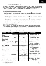
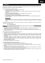
7.5 Интерпретация сообщений ИБП.

Если при работе ИБП возникают неполадки, обратитесь к разделу “Устранение неполадок”, в котором приведены
простые инструкции по восстановлению работы ИБП. Пользователю следует приступить к выполнению процедуры
устранения неполадок в том случае, если на панели управления отображаются аварийные сообщения.

Аварийная сигнализация

В ИБП предусмотрены следующие аварийные сигналы:

Если ИБП переходит в режим работы от АКБ, то с дисплея пропадает символ

,звуковой сигнал подается

каждые 5 секунд;

Если АКБ разряжены, то на дисплее появится соответствующий символ

,звуковой сигнал подается два раза

в пять секунд;

Если ИБП работает в режиме байпас, то на дисплее появится символ

, звуковой сигнал не подается;

Если в ИБП возникла внутренняя неисправность, то на дисплее загорится символ

, подается

непрерывный звуковой сигнал, на дисплей выводится причина аварии.

Отключение звуковой сигнализации

Вы можете отключить звуковую сигнализацию, нажав любую из трех кнопок на панели управления после начала
звуковой сигнализации, за исключением сигнала “Аккумулятор разряжен” – этот звуковой сигнал отключить нельзя. с
Вы также можете выбрать режим «Без звука» в меню настройки ИБП. В этом звуковые сигналы не подаются.

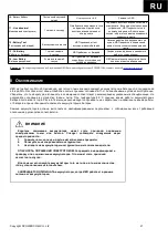
7.6 Устранение неполадок (Коды ошибок)

Сообщение на дисплее Звуковая

сигнализация

Описание неисправности

Способ устранения

01 - High output Voltage

(Высокое напряжение на
выходе)

Постоянный звуковой

сигнал

Высокое напряжение на выходе

ИБП

Выключите ИБП и обратитесь в

авторизованный сервисный центр.

02 - Low Output Voltage

(Низкое напряжение на
выходе)

Постоянный звуковой

сигнал

Низкое напряжение на выходе

ИБП

Выключите ИБП и обратитесь в

авторизованный сервисный центр.

03 - Output Short

(Короткое замыкание на
выходе)

Постоянный звуковой

сигнал

Короткое замыкание на выходе

(в подключенном оборудовании)

Отключите оборудование. Обратитесь в

авторизованный сервисный центр.

04 - Bus Fault

(Высокое напряжение на DC

шине)

2 сигнала каждую

секунду

Высокое напряжение на

внутренней шине постоянного

тока

Отключите оборудование. Выключите

ИБП и обратитесь в авторизованный

сервисный центр.

05 - Over-Temperature

(Перегрев)

Постоянный звуковой

сигнал

Внутренние компоненты ИБП

перегрелись

Убедитесь в том, что вентилятор

работает и вентиляционные отверстия

не перекрыты, а также в том, что

температура воздуха не превышает

40

С. Если причина не в этом,

обратитесь в авторизованный

сервисный центр.

06 - Site wiring Fault

(Неправильное сетевое
соединение)

1 сигнал в секунду

Между нейтралью и землей

присутствует напряжение

Неправильно подключен сетевой

разъем ИБП – переверните

штепсельный разъем. ИБП подключен к

сетевой розетке без заземления.

07 - Output Overload

(Перегрузка на выходе)

Два сигнала в секунду

ИБП перегружен

(питание от электросети).

Потребляемая оборудованием

мощность превышает

номинальную мощность ИБП.

ИБП работает в обходном

режиме.

Отключите от ИБП наименее критичное

оборудование. Если при этом проблема

устранится, ИБП переключится в

нормальный режим.

08 - Over-Charge

(Превышен заряд батарей)

Постоянный звуковой

сигнал

Превышен номинальный заряд

батарей

Отключите оборудование. Выключите

ИБП и обратитесь в авторизованный

сервисный центр.

09 - Charger Failure

(Отказ зарядного устройства)

Постоянный звуковой

сигнал

Зарядное устройство вышло из

строя

Обратитесь в авторизованный

сервисный центр.

Содержание SNT-1000

Страница 1: ...Copyright POWERCOM CO Ltd 1 1000 3000 ON LINE c SENTINEL SNT 1000 SNT 1500 SNT 2000 SNT 3000 SNT 1000 L SNT 1500 L SNT 2000 L SNT 3000 L Revision 1 3 revised April 2020...

Страница 2: ...Copyright POWERCOM CO Ltd 2 C1 1000 1500 2 2000 3000 CE EC EN 62040 1 EN 62040 2 EC 2014 30 ECC 2014 35 EC CE 2020...

Страница 3: ...ERCOM CO Ltd 3 3 5 1 7 2 7 2 1 7 2 2 9 3 9 4 10 5 10 5 1 10 5 2 11 5 3 12 5 4 12 5 5 13 5 6 13 6 13 6 1 14 6 2 RS 232 14 6 3 USB 14 6 4 EPO 14 7 14 7 1 14 7 2 15 7 3 15 7 4 18 7 5 20 7 6 20 8 21 9 22...

Страница 4: ...Copyright POWERCOM CO Ltd 4 Powercom Co Ltd Sentinel 1 2...

Страница 5: ...Copyright POWERCOM CO Ltd 5 40 C 3 5 25 ANSI NFPA 70 26 AWG I 0 15150 69...

Страница 6: ...Copyright POWERCOM CO Ltd 6...

Страница 7: ...Copyright POWERCOM CO Ltd 7 1 1000 3000 2 2 1 1...

Страница 8: ...Copyright POWERCOM CO Ltd 8 RS 232 USB 1 bypass 1 10 15 2 3 3 0 25 50 60 7 2 30 24...

Страница 9: ...Copyright POWERCOM CO Ltd 9 50 220 60 110 0 25 2 2 SNMP 100 90 SNT 1000 3 5 4 SNT 1500 2 4 4 SNT 2000 3 5 4 SNT 3000 2 4 4 3...

Страница 10: ...Copyright POWERCOM CO Ltd 10 10 0 40 20 4 15 C 25 C 6 8 8 15 30 6 30 45 3 5 5 1 4 25 6 12 15 C 25 C 100 50...

Страница 11: ...Copyright POWERCOM CO Ltd 11 5 2 2 1 2 2 2 2 1 2 1 2...

Страница 12: ...Copyright POWERCOM CO Ltd 12 5 3 8 3 6 3 Plug Play 5 4 4...

Страница 13: ...Copyright POWERCOM CO Ltd 13 5 5 5 1 2 3 4 5 5 6 208 220 230 240 230 On Off Off On Off Off On Off Off On Off On On Off Off On Off Off 7 2 6 2 RS 232 USB RS 232 USB USB RS 232 USB RS 232 SNMP AS 400...

Страница 14: ...O Ltd 14 6 1 RS 232 USB RS 232 SNMP Simple Network Management Protocol SNMP 6 2 RS 232 RS 232 9 D sub 4 2 TxD TxD 3 RxD RxD 5 Common 6 CTS 8 DCD 9 RI 12 6 3 USB USB USB RS 232 USB A B 6 4 EPO EPO EPO...

Страница 15: ...Copyright POWERCOM CO Ltd 15 7 2 1 3 5 2 20 3 2 10 6 7 3...

Страница 16: ...Copyright POWERCOM CO Ltd 16 7 0 24 25 49 50 74 75 100 0 24 25 49 50 74 75 100...

Страница 17: ...OWERCOM CO Ltd 17 O P VOLT xxxV O P FREQ xx x Hz I P VOL T xxxV I P FREQ xx x Hz BAT VOLT xx xV O P W xx xW O P flashing x x x W O P VA xx xVA O P x x A RATING xx xKVA UPS VERSION xx x O P VOLT xxxV 1...

Страница 18: ...Copyright POWERCOM CO Ltd 18 7 4 8...

Страница 19: ...Copyright POWERCOM CO Ltd 19 9...

Страница 20: ...t POWERCOM CO Ltd 20 7 5 5 7 6 01 High output Voltage 02 Low Output Voltage 03 Output Short 04 Bus Fault DC 2 05 Over Temperature 40 06 Site wiring Fault 1 07 Output Overload 08 Over Charge 09 Charger...

Страница 21: ...Copyright POWERCOM CO Ltd 21 10 Battery Failure 11 Line abnormal 1 12 Battery Test 13 On Battery 1 5 14 Low Battery 2 5 POWERCOM email info service pcm ru 8 25 4 6 12 1 2 3...

Страница 22: ...Copyright POWERCOM CO Ltd 22 9 24 30 9 1 POWERCOM 10 kVA On line 4 kVA Powercom On line 4 kVA POWERCOM...

Страница 23: ...140 300 50 160 300 75 180 300 100 36 12 7 3 36 12 9 3 72 12 7 6 72 12 9 6 2 4 7 10 4 90 208 220 230 240 2 50 60 0 25 0 99 90 95 2 5 4 105 120 30 121 150 10 101 109 10 110 120 3 0 0 1 45 50 1 5 RS 232...

Страница 24: ...150 10 101 109 10 110 120 3 0 0 1 45 50 1 5 RS 232 USB SNMP 428x425x84 428x635x84 8 6 9 5 14 1 14 4 11 4 12 2 18 2 18 5 6 IEC320 C13 6 IEC320 C13 8 IEC320 C13 1 19 3500 0 95 0 40 15 25 12 50 1000 150...

Страница 25: ...U P S On Line SNT 1000 SNT 1500 SNT 2000 SNT 3000 SNT 1000L SNT 1500L SNT 2000L SNT 3000L USER MANUAL...

Страница 26: ...cur in some installations If by turning on and off it can be deduced that your radio or television reception is found to be influenced by harmful interference from the equipment it is recommended to u...

Страница 27: ...ation 9 4 1 General Description 9 4 2 System Configuration 10 4 3 Panel overview 10 4 4 UPS Control 11 4 5 UPS Status Display 13 4 6 UPS Configuration 14 5 UPS Monitoring Connection 15 5 1 Connect UPS...

Страница 28: ...hut down may occur CAUTION Ensure the total leakage current of UPS and the connected equipment under 3 5mA CAUTION Ensure UPS connects to grounded main power with a fuse or circuit breaker protection...

Страница 29: ...rating ONLY 2 Introduction The information provided in this manual covers the ON LINE UPS 1KVA 3KVA uninterruptible power system UPS This manual contains basic functions operating procedures and emer...

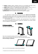
Страница 30: ...5 All rights reserved All trademarks are property of their respective owners Simply attach the ear to the matching side of UPS and use the screw to lock the ear for further application...

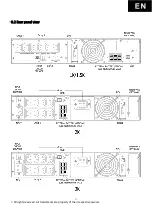
Страница 31: ...6 All rights reserved All trademarks are property of their respective owners 3 2 Rear panel view...

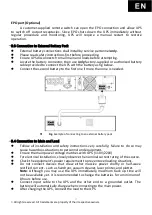
Страница 32: ...n one is needed Fig Example of connecting to an external battery pack 3 4 Connection to Main and Load Follow all installation and safety instructions very carefully failure to do so may cause hazardou...

Страница 33: ...ghts reserved All trademarks are property of their respective owners Should computer or alarm connections be used refer to the UPS monitoring connection chapter for further detail The installation is...

Страница 34: ...ected range user adjustable Free Run Mode enlarges input frequency acceptance up to 45Hz 65Hz but fixes output frequency to 50Hz 220V and 60Hz 110V with 0 25Hz Free Run Mode designs for large power va...

Страница 35: ...d battery make up the system Depending on site and load requirements certain additional options are available as tailored solutions Please consider the following when planning your UPS system The tota...

Страница 36: ...iled Check your battery Fault UPS Internal external fault Error code will display beside it Generator Mode UPS is operating on Generator mode Overloading UPS suffers an overload problem Output exceeds...

Страница 37: ...play status There are 10 statuses available for users c Enter function only uses during settings Check the button for more detail d If UPS idles for 20 seconds the display will return to the main stat...

Страница 38: ...y breaker and wait till all fans completely shut down In an emergency use the EPO located on the rear panel 4 5 UPS Status Display UPS status shows in normal display mode From here you can go to the U...

Страница 39: ...r function If UPS is idle over 10 seconds the display will return to the main menu Function Setting Icon Available Setting Default Setting Setting Output Voltage 208V 220V 230V 240V 230V 100V 110V 115...

Страница 40: ...SB Port or RS232 port only one port will function at a time 5 2 Connect UPS with interface Slot Optional SNMP Card allows UPS management and monitoring over a network or internet For more information...

Страница 41: ...t the UPS to function smoothly 6 1 Transportation Please handle UPS with extreme caution since the battery contains a high amount of energy Keep the unit in position as marked on the packaging and nev...

Страница 42: ...screw and metal battery cover disconnect battery cable then remove the battery 3 Replace with the same type and quantity of battery 4 Reinstall the new battery and push it into the UPS 5 Reinstall the...

Страница 43: ...ss on OFF and press Enter again UPS will return to Line Mode APP A Trouble Shooting Troubleshooting procedures give simple instructions in determining UPS malfunctions Start the troubleshooting proced...

Страница 44: ...onnected equipment power requirements exceed UPS provision UPS will switch to bypass mode when overload in Line mode Shut off less essential equipment connected to UPS UPS automatically switches back...

Страница 45: ...25 Hz Transfer Time 0 ms Harmonic Distortion 2 5 THD at Linear Load Crest Factor 3 1 EPO Function Yes Protection Overload Line Mode 105 120 for 30 seconds 121 150 for 10 seconds Battery Mode 101 109 f...

Страница 46: ...n 2 5 THD at Linear Load Crest Factor 3 1 EPO Function Yes Protection Overload Line Mode 105 120 for 30 seconds 121 150 for 10 seconds Battery Mode 101 109 for 10 seconds 110 120 for 3 seconds Surge P...

Отзывы: