background image

www.sentera.eu

MIW-RTVS1-EN-000 - 03 / 11 / 2020

11 - 12

back to the table of contents

TRANSFORMER FAN SPEED CONTROLLER WITH 
MODBUS RTU COMMUNICATION

RTVS1

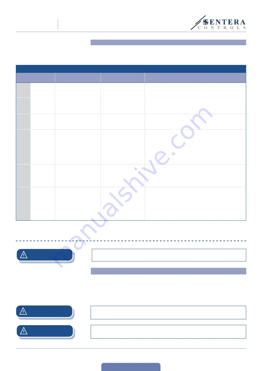
Explanation of specific Modbus registers

The unit has factory pre-set parameters written in Modbus map. It can function 
without any other settings. However, there are some special registers you may need 
to set depending on you combination of products. These are listed in 

Table 2

  below.    

Table 2  Voltage steps

Modbus holding 
registers

Description

Values 

Remark

11

Control Set

Automatic control – takes value 

from sensor. Manual Control – 

takes value from register 12

Auto Forward mode;

Manual mode;

Auto Reverse mode

It is possible to change the control of the article only when the switching 

of the current command has finished. 

13

Output Update 

Interval

Time delay to update the 

output in automatic mode

5 s—600 s

If the value of the sensor connected is changing too fast this is the 

register that provides control of the time between two consecutive 

switching.   

16

Hysteresis delta

The difference between 

the upwards switching and 

downwards switching step 

percentage

2—10 %

This value is subtracted from the threshold when the article is switching 

from high to low input value. Hysteresis value is 2 – 10%, it means for  

threshold 20%, the “threshold – hysteresis” = 18% for Δ = 2%. 

17

Communication 

Lost Output 

State

Set output when Modbus 

communication is lost

OFF;

Last step selected

Set to 0 = OFF, when there is Modbus Timeout set, when the device 

encounters Timeout - RTVS1 enters STOP mode, output is 

0. If the remote sensor is lost – device enters state 0 = OFF. Both 

communications lost, article goes to OFF. 

When set to 1 = Last step selected, on Modbus Timeout occurrence and 

sensor is connected – article continues to operate in regarding of the 

input from the sensor, if sensor is lost – the article stays on the last 

step selected. If both communications are lost, device stays on the last 

step selected. 

In Auto modes, if there is no communication to the control/monitoring 

station, the article continues to operate autonomously while the sensor 

is connected.

18

Sensor output 

register value 

number

Select which sensor output will 

be used as input to the device

Digital potentiometer;

Temperature;

Relative Humidity;

CO

2

/CO

2

eq;

CO/TVOC;

NO

2

Sensor output register value number, define which sensor value will be 

taken for control of the device switching. The restrictions that apply 

are for Sentera Sensors only, and the SPV device. When SPV device is 

connected this value becomes automatically 1 and cannot be changed 

until other sensor is connected.

21—25

Input value 

step 1—5

Input value to switch to output 

steps 1—5

Switches to output step X at 

X % input value and steps 

down to output previous step 

at X % - Hysteresis delta 

(HR16) set

Input Value Step X – the steps will be activated over these thresholds. 

If register value is 0 – this step will be skipped as a holding step, but 

it will be used as intermediate step if needed to switch to upper/lower 

step. Minimum difference between steps thresholds is 11%, that way any 

overlapping of the switching and the hysteresis is avoided.

VERIFICATION OF INSTALLATION

Use only tools and equipment with non-conducting handles when working on 
electrical devices.

ATTENTION

 Safe operation depends on proper installation. Before start up, ensure the following:


The mains supply is connected correctly.


Protection is provided against electrical shock.


The cables are the appropriate size and fuse-protected.


There is sufficient air flow around the unit.


ATTENTION

The unit is supplied with electrical energy at voltages high enough to inflict personal 
injury or threat to health. Take the relevant safety measures. 

ATTENTION

Disconnect and confirm that there is no live current flowing to the unit before servicing.

Содержание RTVS1

Страница 1: ...Mounting and operating instructions TRANSFORMER FAN SPEED CONTROLLER WITH MODBUS RTU COMMUNICATION RTVS1 ...

Страница 2: ...SCRIPTION 4 ARTICLE CODES 4 INTENDED AREA OF USE 4 TECHNICAL DATA 4 STANDARDS 4 WIRING AND CONNECTIONS 5 MOUNTING INSTRUCTIONS IN STEPS 6 OPERATING INSTRUCTIONS 9 VERIFICATION OF INSTALLATION 11 TRANSPORT AND STORAGE 12 WARRANTY AND RESTRICTIONS 12 MAINTENANCE 12 TRANSFORMER FAN SPEED CONTROLLER WITH MODBUS RTU COMMUNICATION RTVS1 ...

Страница 3: ...t is as dry as possible avoid condensation All installations shall comply with local health and safety regulations and local electrical standards and approved codes This product can only be installed by an engineer or a technician who has expert knowledge of the product and safety precautions Avoid contacts with energised electrical parts Always disconnect the power supply before connecting servic...

Страница 4: ...mounted Selection can be made via RTVS1 Modbus holding register 20 TECHNICAL DATA Supply voltage 230 VAC 50 60 Hz Modbus RTU communication TK monitoring for thermal motor protection Operating modes Automatic from low to high or from high to low Fan speed based on input from external Sentera sensor or potentiometer connected to the RJ45 master socket Manual Fan speed based on user input via Modbus ...

Страница 5: ... be activated manually via Modbus Holding register 14 or automatically in case of an RTVS1 alarm L N INPUT Power supply neutral L Power supply phase 230 VAC 50 60 Hz TK Input TK monitoring for thermal motor protection TK RJ45 master socket to connect a Sentera HVAC transmitter for demand based fan speed control in automatic mode Pin 1 24 VDC Supply voltage Pin 2 Pin 3 A Modbus RTU communication si...

Страница 6: ...he warmer the device will get For example in a technical room the correct installation height can be of great importance Do not install the controller above heating equipment or heat sources 3 3 If maximum ambient temperature cannot be adhered to please provide extra forced ventilation cooling Not respecting the abovelisted rules can reduce service life and relieves the manufacturer of any respons...

Страница 7: ...the 3SModbus software or Sensistant For the default factory setting see the Modbus register map The desired fan speed can be adjusted via Modbus holding register 14 For the complete Modbus register data refer to the product Modbus Register Map which is a separate document attached to the article code on the website and contains the registers list NOTE Optional settings 1 In automatic mode a Senter...

Страница 8: ...lled on your computer The Modbus to USB converter CNVT USB RS485 allows you to connect a Sentera device to the USB port of your computer and to monitor or adjust the different parameters see Application examples 1 and 2 Application example 1 Manual mode control via Modbus holding register 14 CNVT USB RS485 Master RTVS1 A B GND Application example 2 Automatic mode demand based ventilation RTVS1 Sla...

Страница 9: ...orward mode 3 1 Manual mode The value is taken by Holding Register 12 where you can set the desired output step see the steps and corresponding voltages in Table 1 above 3 2 Automatic modes When Auto mode has been selected the controller changes the five speeds automatically according to the values measured by the sensor connected to the RJ45 master socket There are two automatic modes 3 2 1 Autom...

Страница 10: ... diagram below for an example with steps from 2 to 5 An example of Auto Reverse mode the steps threshold configuration is as follows Step 1 0 Step 2 75 Step 3 50 Step 4 25 Step 5 1 can be as low as 0 1 is given in Fig 5 below When the Input value is above 1 device switches to Step 5 above 25 Step 4 above 50 Step 3 above 75 Step 2 up to 100 When the Input value decreases the hysteresis delta is sub...

Страница 11: ... the sensor if sensor is lost the article stays on the last step selected If both communications are lost device stays on the last step selected In Auto modes if there is no communication to the control monitoring station the article continues to operate autonomously while the sensor is connected 18 Sensor output register value number Select which sensor output will be used as input to the device ...

Страница 12: ...n manufacturing Any modifications or alterations to the product after the date of publication relieve the manufacturer of any responsibilities The manufacturer bears no responsibility for any misprints or mistakes in this data MAINTENANCE In normal conditions this product is maintenance free If soiled clean with a dry or damp cloth In case of heavy pollution clean with a non aggressive product In ...

Отзывы: