www.sentera.eu
MIW-RSTHM-2-EN-000 - 15 / 01 / 2019
6 - 10
back to the table of contents
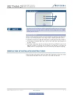
Fig. 1 Snap-fits release
Fig. 2 Mounting dimension
Fig. 3 Mounting position
2x Ø
6
59,8
9,
8
74,5
104,5
20
104,5
25,
6
70,
5
Correct
Incorrect
Position at min. 1,5 m
from the floor
4.
Do the wiring according to the wiring diagram (see
Fig. 4
).
Fig. 4 Wiring diagram
/B
A
GN
D
24 VD
C
8 mm
8 mm
8 mm
8 mm
RJ45
1 2 3 4 5 6 7 8
1
2
3
4
5
6
7
8
24 VDC
GND
A
/B
Supply voltage
24 VDC
Ground
Modbus RTU
communication,
signal A
Modbus RTU
communication,
signal /B
/B
A
GND
24 VDC
8 mm
8 mm
8 mm
8 mm
RJ45
1
2
3
4
5
6
7
8
1
2
3
4
5
6
7
8
5.
Put back the cover and snap it in.
6.
Switch on the mains supply.
5.
RSTHM-2
COMBINED T AND RH
ROOM TRANSMITTER


