background image

www.sentera.eu

MIW-RSTHM-2-EN-000 - 15 / 01 / 2019

2 - 10

Table of contents

SAFETY AND PRECAUTIONS 

3

PRODUCT DESCRIPTION 

4

ARTICLE CODES 

4

INTENDED AREA OF USE 

4

TECHNICAL DATA 

4

STANDARDS 4

OPERATIONAL DIAGRAMS 

5

MOUNTING & OPERATING INSTRUCTIONS IN STEPS 

5

OPERATING INSTRUCTIONS 

7

VERIFICATION OF INSTALLATION INSTRUCTIONS 

8

MODBUS REGISTER MAPS 

8

TRANSPORT AND STORAGE 

10

WARRANTY AND RESTRICTIONS 

10

MAINTENANCE 10

RSTHM-2

COMBINED T AND RH 
ROOM TRANSMITTER

Содержание RSTHM-2

Страница 1: ...Mounting and operating instructions RSTHM 2 COMBINED T AND RH ROOM TRANSMITTER ...

Страница 2: ...DES 4 INTENDED AREA OF USE 4 TECHNICAL DATA 4 STANDARDS 4 OPERATIONAL DIAGRAMS 5 MOUNTING OPERATING INSTRUCTIONS IN STEPS 5 OPERATING INSTRUCTIONS 7 VERIFICATION OF INSTALLATION INSTRUCTIONS 8 MODBUS REGISTER MAPS 8 TRANSPORT AND STORAGE 10 WARRANTY AND RESTRICTIONS 10 MAINTENANCE 10 RSTHM 2 COMBINED T AND RH ROOM TRANSMITTER ...
Страница 3: ... possible avoid condensation All installations shall comply with local health and safety regulations and local electrical standards and approved codes This product can only be installed by an engineer or a technician who has expert knowledge of the product and safety precautions Avoid contacts with energised electrical parts always treat the product as if it is live Always disconnect the power sup...

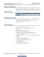
Страница 4: ...oor use only TECHNICAL DATA Maximum power consumption 0 0 312 W Nominal power consumption in normal operation 0 0 234 W Imax 13 mA Selectable temperature range 0 50 C Selectable relative humidity range 5 85 Ambient light sensor with adjustable active and standby level Bootloader for updating the firmware via Modbus RTU communication 3 LEDs for status indication Accuracy 0 4 C 0 50 C 3 rH 5 85 rH d...

Страница 5: ...G INSTRUCTIONS IN STEPS Before you start mounting the RSTHM 2 room transmitter read carefully Safety and Precautions Choose a smooth surface for installation a wall panel and etc Follow these steps 1 Using a flat screwdriver remove the front white cover by releasing the snap fits on its both sides see Fig 1 Snap fits release 2 Insert the crimped RJ45 cable through the opening on the rear plate and...

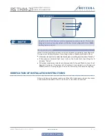
Страница 6: ...floor 4 Do the wiring according to the wiring diagram see Fig 4 Fig 4 Wiring diagram B A GND 24 VDC 8 mm 8 mm 8 mm 8 mm RJ45 1 2 3 4 5 6 7 8 1 2 3 4 5 6 7 8 24 VDC GND A B Supply voltage 24 VDC Ground Modbus RTU communication signal A Modbus RTU communication signal B B A GND 24 VDC 8 mm 8 mm 8 mm 8 mm RJ45 1 2 3 4 5 6 7 8 1 2 3 4 5 6 7 8 5 Put back the cover and snap it in 6 Switch on the mains s...

Страница 7: ... enter Boot mode put a jumper onto pins 3 and 4 of the P1 header and restart the power supply see Fig 5 Once Boot mode is activated the firmware can be updated via SM Boot application part of 3SModbus software suite or Sensistant Fig 5 P1 header 1 2 3 4 5 Put a jumper onto pins 1 and 2 and wait for at least 5 seconds to reset the Modbus communication parameters 1 2 3 4 5 Put a jumper onto pins 3 a...

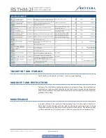
Страница 8: ...in luxes If the measured light level is below the Standby level Input Register 6 indicates Standby If the measured ambient light level is above the Active level Input Register 6 indicates Active If the measured ambient light level is between the Active and Stand by level Input Register 6 indicates Low intensity therefore it is advisable to set Active and Standby levels in Holding Registers 34 and ...

Страница 9: ...int Flag indicates that measured temperature is outside set range limit values Set to 1 when the measured value is outside the temperature range limit values defined by holding registers 14 and 15 0 1 0 1 Temperature range is OK Temperature range is too high low 18 Relative humidity range limit flag unsigned int Flag indicates that measured relative humidity is outside set range limit values Set t...

Страница 10: ...y connecting NBT 0 1 0 0 1 NBT disconnected NBT connected 31 33 Reserved return 0 34 Active light level unsigned int The ambient light level above which Active is indicated in input register 6 0 32 000 100 100 100 lx 35 Standby light level unsigned int The ambient light level below which Standby is indicated in input register 6 0 32 000 10 10 10 lx 36 Modbus registers reset unsigned int Resets Mod...

Отзывы: