ENGLISH
Pag. 12
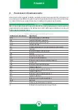
2. Power on and operation
When the detector is powered on the display will show different messages according to the
gas detector model and the gas it has been calibrated for.
The values appearing on the display when the unit is powered on might differ from what
listed in Table 2 after as the various models have different full scales, alarm thresholds, and
outputs.
Always refer to the identification label stuck on the detector and the programming dip-swi-
tches (see SMART3G user manual) that define the output alarm thresholds and the detector
full scale.
Table 2) Display indications at power ON
Display indications
Meaning
S 3G
Gas detector of SMART3G series
VEr
Gas detector firmware version
3.10
Example value of firmware version
4.20
4-20 mA output
Idi
Detector equipped with optional board for serial output
Adr
Address
1
Example detector address
bPS
Baurate
9.6
Detector baudrate
VIn
Power supply
24.8
Example power supply value
F.S.
Fullscale
100
Example fullscale value
tHr1
Alarm threshold 1
10
Example Alarm threshold 1 value
tHr2
Alarm threshold 2
20
Example alarm threshold 2 value
tHr3
Alarm threshold 3
10
Example alarm threshold 3 value
HEAT
Warmup
12
Example residual warmup time
0
Example of gas reading
WARNING!
Содержание SMART3G
Страница 4: ...ITALIANO Pag iv...
Страница 14: ...ENGLISH Pag 10...

