17
16
Multipurpose Wireless Microphone Digital Class-D PA Speaker System
Note On Unit Installation
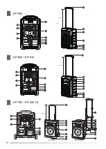
1. To assembly this unit should be away from ground (1 meter ~ 1.5 meter) to get best position.
Option with tripod stand (ST-3B)
2. Adjust the volume to the minimum position (Main volume control/CD or TAPE volume) by any volume control.
3. When charging the batteries, the(
Ⅱ
) green light indicator is blinking. And when the rechargeable batteries are fully
charge, the green light indicator will be solid green.
4. The receiver of this unit can be changed frequencies which is high quality product with easy operation.
5. The Extension speaker system must be to 4
Ω
/80W handling and power impedance to be connected and insert into
6.3mm external jack.
1. Make sure positive and negative when changing the rechargeable batteries.
2. To keep batteries service longer, switched off while not using this unit.
3. No need to connect with power cord ,
the
duration
of
operation
with
speaking
mode
could
be
3-10
hours
(
It
depends
on
volume
)
When
the
green
signal
remain
last
,
it
shows
low
battery
status
,
please recharge the battery right
away and switch the power as off, Flashing green
–
Indictor Recharging the battery.Solid
green signal Fully
battery
power
.
4. Remove the batteries if you do not plan to use the unit for a long period of time. To keep full batteries, please
charging once between 2-3 month without fixed schedule.
–
Note on Unit:
1. No altering or remodeling, this can cause malfunctioning.
2. No dropping or strong impacts, this may damage the unit.
3. Do not leave the unit exposed to direct sunlight for long periods of time.
4. Do not use trolley on the ragged ground and avoid any damage. Technical service: www.ecen.com.tw
Troubleshooting And Maintenance Guide
Chanel Specifications
Micphone Specifications
Federal Communication Commission Interference Statement
This equipment has been tested and found to comply with the limits for a Class B digital device, pursuant to Part 15 of the
FCC Rules. These limits are designed to provide reasonable protection against harmful interference in a residential installation.
This equipment generates, uses and can radiate radio frequency energy and, if not installed and used in accordance with
the instructions, may cause harmful interference to radio communications. However, there is no guarantee that interference
will not occur in a particular installation. If this equipment does cause harmful interference to radio or television reception,
which can be determined by turning the equipment off and on, the user is encouraged to try to correct the interference by one
of the following measures:
●
Reorient or relocate the receiving antenna.
●
Increase the separation between the equipment and receiver.
●
Connect the equipment into an outlet on a circuit different from that to which the receiver is connected.
●
Consult the dealer or an experienced radio/TV technician for help.
FCC Caution
: To assure continued compliance, any changes or modifications not expressly approved by the party responsible
for compliance could void the user's authority to operate this equipment. (Example use only shielded interface cables when
connecting to computer or peripheral devices).
Warning
Explanation Of Graphical Symbols
The lightning flash with arrowhead symbol, within an equilateral triangle, is
intended to alert the user to the presence of uninsulated dangerous voltage
within the products enclosure that may be of sufficient magnitude to
constitute a risk of electric shock to humans.
The exclamation point, within an equilateral triangle, is intended to alert the
user to the presence of important operating and maintenance(servicing)
instructions in the literature accompanying the appliance.
CAUTION
RISK OF ELECTRIC SHOCK
DO NOT OPEN
CAUTION
:To reduce the risk of electric shock, do not remove the cover, No user serviceable
parts inside. Refer servicing to qualified personnel.
WARNING
:To prevent fire or electric shock, do not expose this equipment to rain or moisture.
Frequency range
Carrier Frequency Range
Stability
Deviation
Dynamic range
S/N Ratio
T.H.D.
Squelch Circuit
Frequency Response
Receiver Mode
Wireless Microphone Capsule Type
Wireless Transmitter Ratio
Transmitter Battery
UHF PLL
UHF 600-960MHz
6
0.005%,provide redeem temperate
6
40KHz, with level Limiting circuit controlled
>110dB
>105dB
<0.5%
Pilotone squelch / PLL Synthesized Receiver /
Non-Diversity
50Hz~18KHz
6
3dB
Quartz and Tone Squelch True Diversity/
Single Receiver/Non-Diversity or PLL System
Dynamic Capsule or Condenser Capsule
Approx 10mW
AA No 3 Batteries (2 pcs) / 9V Battery (1pc)
MODEL
Carrier frequency range
Pre-programmed Frequency
Frequency stability
Frequency response
Antenna
Battery
Weight
UPL-83
600-960MHz
Preset 16 Channels
<0.005%
50Hz-18KHz(
±
3dB)
External antenna
1.5v x 2 or
1.2V x 2(AA UM-3)
100g
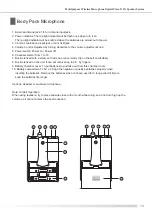
Instruction For Changing Battery
Note: Diagram 1.
1. Please switch power off before start to changing batteries.
2.Take out 4 pieces of screws and remove batteries plates from main panel board and take batteries out.
Install batteries 12V/4.5A into battery compartment.
3.Make sure the battery pack is properly inserted then closed the cover by tight up the screws.
To connected red line into positive R1 red line terminal, black line into
negative B2 black line terminal, to gathered negative B1 and positive R2 to connect each and inserted.
4.Note: Make sure the pole with color. Refer to Instruction for Changing Battery Diagram 1. Do not make error
attached or otherwise causing damage or power is not working in perfect condition. To keep full batteries,
if you do not plan to use the unit for a long period of time.
Red
Black
Transmitter Model
Outlood design
Microphone capsule
Carrier Frequency range
Frequency Stability
Frequency Response
Antenna
S/N Ratio
RF Output Power
Currency Consumption
Battery
Weight
Handheld
600-960MHz
±
0.005%
50Hz-18KHz(
±
3dB)
Built in
80dB overall
10mW MAX.
100mA
±
10mA
UH-816
1.5V x 2 Pecs
230g
Dynamic(EP-900 device ECM)
Содержание EP-2001G series
Страница 2: ......

