background image

2

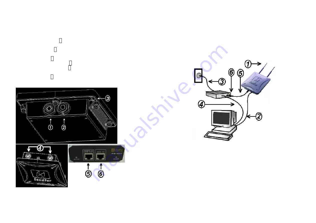
1.2  Locate the Access Point and Inline Power
Injector Ports

z


Special

 Ethernet port 1 for connecting the MIL-C-5015 style Ethernet

Cable

z


Special

 serial port 2 for connecting the MIL-C-5015 style RS-232

console port cable

z

 Grounding 

port 

3.

z


Special N-Type connector 4 for connecting the antenna or RF cable.

z


Power & Data output port 5 for connecting the other of the MIL-C-
5015 style Ethernet Cable

z


Data input port 6 for connecting the Ethernet Cable to a Hub Switch
Router or a PC.

3

1.3  Installing the Antennas

Step 1:


With the unit powered off, attach the dipole antenna to the antenna

connector as shown in 

Figure 1.3

.

NOTE: 

Do not over-tighten; finger tight is sufficient. Position the antenna

vertically for best omni-directional signal reception.

Figure 1.3

.

Before installing your WLAN system, we recommend that you test the
Access Point using the dipole antenna included in your package. Once
testing is completed, install your Access Point for use with the appropriate
antenna for your application.

1.4  Installing the Console Port Cable

Step 2:

 Attach the Console Port cable to the Serial Port. Attach the other

cable end to the Serial Port on a PC running a terminal emulation program,

Содержание AP-8110

Страница 1: ...9 2 4 WIRELESS ACCESS ROUTER WITH STATIC IP ETHERNET CONNECTION 10 CHAPTER 3 WEB ACCESS 11 CHAPTER 4 CONFIGURATION 15 4 1 INTRODUCTION 15 4 1 1 Basic Configuration Steps 15 4 2 SYSTEM SETUP 16 AFTER...

Страница 2: ...2 Administration 48 CHAPTER 8 REGULATORY COMPLIANCE INFORMATION 49 1 Chapter 1 Hardware Installation This chapter describes the procedures for installing the SendFar Outdoor Access Point 1 1 Before Y...

Страница 3: ...Installing the Antennas Step 1 With the unit powered off attach the dipole antenna to the antenna connector as shown in Figure 1 3 NOTE Do not over tighten finger tight is sufficient Position the ant...

Страница 4: ...the access point Step 6 Plug the RJ 45 Ethernet connector the other end of the Special Ethernet cable into the Power Data Output Port on the front of the Inline Power Injector When the Access Point re...

Страница 5: ...ne through a centralized Access Point To show some possibilities of wireless topologies the following examples are provided 1 Wireless Access Bridge 2 Wireless Access Router with PPPoE Ethernet connec...

Страница 6: ...n DHCP server on the OWAP and assign IP address to PC1 PC2 and PC3 5 Set Wireless parameters on client stations PC1 PC2 and PC3 SSID wireless 9 2 3 Wireless Access Router with dynamic IP Ethernet conn...

Страница 7: ...1 Identify the IP Address assigned to the unit However the IP Address may be changed and you cannot connect the unit using the default IP Address In this case you must identify the OWAP IP Address bef...

Страница 8: ...nfigure each item 1 Open your browser and enter the IP Address 2 Press ENTER and the OWAP Login screen appear 13 Figure 3 2 Login Screen 3 Enter root in the User Name and the Password fields And then...

Страница 9: ...reless Router with DHCP Client Ethernet connection 4 Wireless Router with Static IP Ethernet connection 4 1 1 Basic Configuration Steps Modify the Default Settings and Apply the New This section will...

Страница 10: ...17 Figure 4 2 General Configuration System Setup 2 Host Information Host Name The Host Name is not an essential setting but it helps identify the device in network Use this setting to assign a name to...

Страница 11: ...the Ethernet interface s IP address Subnet Mask Enter an IP subnet mask to identify the sub network so the IP address can be recognized on the WAN NAPT performs on which interface There are three inte...

Страница 12: ...P Primary DNS Server IP Enter the Primary Domain Name Server IP Address Secondary DNS Server IP Enter the Secondary Domain Name Server IP Address After that click FINISH at the bottom of this page to...

Страница 13: ...ries list 4 To modify or delete a virtual server entry click the select button beside the entry index number and click Modify or Delete 5 To add another entry to the Virtual Server Mapping Pool repeat...

Страница 14: ...e 4 3 2 Fixed Host Entries Figure 4 5 shows the general DHCP parameters and the fixed host entry table Default fixed host entry pool is empty 1 Click Add The Fixed Host Entry Edit page Figure 4 6 appe...

Страница 15: ...Access Right and Community field Validity Select Enable or Disable to control this community 27 Access Right Select a command from the pull down menu for this field Community Enter the password relate...

Страница 16: ...t is 1600 frag Threshold default is 1600 SSID default is wireless and Station Name default is ap that are suitable for your radio network and then you can clicked radio button to disable WEP or enable...

Страница 17: ...or 64 and 128 bits WEP KEY encryption and then click KeyGen to generate the WEP64 WEP128 key patterns WEP Disable or enable 64 128 bit WEP services Default Key Select an encryption key from the pull d...

Страница 18: ...can also click ADD DELETE MODIFY button to maintain this MAC address table After that click FINISH at the bottom of this page to complete the modification of this page Figure 4 12 33 4 7 Utility 4 7...

Страница 19: ...the New Settings 1 Click Utility Administration select the Save then Restart to apply the new configuration settings 2 Click FINISH To take effect the previous configuration changes Hint It takes abou...

Страница 20: ...ed the Operation Mode Interface IP Net mask and brief wireless parameters if the operator turn on the DHCP or PPPoE services you can also see the related information on here Services Information This...

Страница 21: ...AP this association table includes the associated station MAC address and the corresponded connection time 39 5 4 Statistic Information Click Running Status Statistic Info Figure 5 3 shows the statis...

Страница 22: ...Sensitivity 84dBm for 11Mbps 8 PER Packet Error Rate 90dBm for 2Mbps 8 PER Packet Error Rate RF Output Power 19dBm typically including antenna gain ETSI 14 2dBm typically including antenna gain FCC R...

Страница 23: ...ass IP Address 192 168 1 1 Wireless Interface Address Subnet Mask 255 255 255 0 IP Address 192 168 2 1 Ethernet WAN Interface Address Subnet Mask 255 255 255 0 IP Address 192 168 2 1 Ethernet LAN Inte...

Страница 24: ...tart IP IP starting address 192 168 1 240 DHCP End IP IP ending address 192 168 1 249 Interface 1 Wireless 2 Ethernet Wireless Ethernet Address Fixed Host Entries Max 10 IP Address Empty 45 7 1 4 SNMP...

Страница 25: ...oyed 1 Channel USA 1 11 Europe 1 13 1 RTS Threshold Set RTS Request To Send threshold value 1600 Fragmentation Threshold Set fragmentation threshold value 1600 SSID Wireless LAN service area identifie...

Страница 26: ...with any other antenna of transmitter Interference Statement This equipment has been tested and found to comply with the limits for a Class B digital device pursuant to Part 15 of the FCC Rules and Re...

Страница 27: ...high power systems are operated strictly as a point to point system Systems operating as a point to multipoint system or use non directional antennas cannot exceed 30dBm EIRP power requirement under a...

Отзывы: