SEM PHTS108 Скачать руководство пользователя страница 13

A2538-003/01 March 2020


SEMCO Proprietary Information


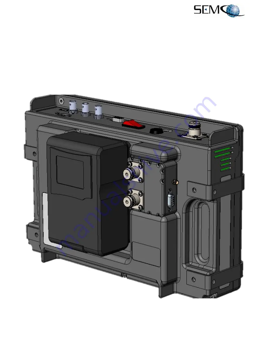
2.2.1  Optional Dual RF Output and Dynamic Combiner Test Feature 
 

Figure 2-7 illustrates the Dual RF Output and Dynamic Combiner Test Option.  This option is a module designed 
to attached to the rear of the PHTS108 as shown, with module I/O provided by the “D” connector Cable Harness 
Assembly.  The module provides 2 modulated RF outputs and the capability to select and automatically vary 
the 2 RF (CH1 and CH2) signal levels (Fade Depth), vary the rate at which these differing levels are changing 
(Fade Rate) and vary the phase relationship between these 2 RF signals (Phase Shift). 
 
Changing the Fade depth, Fade Rate and Phase between these 2 RF outputs provides the ability to dynamically 
test a pre-d Diversity Combiner in a dual channel telemetry receiver and ensure proper performance using a 
simulated real-world mission scenario. 


Figure 2-7 

Dual RF Output and Dynamic Combiner Test Option 


Содержание PHTS108

Страница 1: ...ION EITHER IN WHOLE OR IN PART OR MANUFACTURE PRODUCE SELL OR LEASE ANY PRODUCT COPIED FROM OR ESSENTIALLY REPRODUCED FROM THE INFORMATION CONTAINED IN THIS DOCUMENT WITHOUT THE EXPRESSED WRITTEN APPR...

Страница 2: ...nt Use standard and accepted safety practices with respect to operating commercial electrical equipment at all times to avoid the risk of personal injury or death EMI EMC The PHTS108 complies with all...

Страница 3: ...38 003 01 March 2020 SEMCO Proprietary Information LIST OF EFFECTIVE PAGES Page Change Date Page Change Date Initial Release A2538 001 05 01 2018 All AllAll A2538 002 04 01 2019 All A2538 003 03 01 20...

Страница 4: ...at Binary File Directly from USB Media Source 22 3 2 4 2 Loading and Saving a Flat Binary File to the PHTS108 Hard Drive 26 3 2 5 Using an External Data Source 28 3 2 6 Bit Synchronizer Control Panel...

Страница 5: ...inary File 16 3 14 WSI Chapter 10 File Utilities GUI 18 3 15 Opening the WSI Chapter 10 File Utility 18 3 16 Selecting the Chapter 10 File 19 3 17 Viewing the Chapter 10 File Summary Information 19 3...

Страница 6: ...d Bit Error Insertion 34 3 46 Frame Sync Control Panel 34 3 47 Frame Sync Word Selection 35 3 48 Frame Sync Word Length Entry 35 3 49 Invalid Frame Sync Word Length Entry 36 3 50 Frame Sync Bits per W...

Страница 7: ...tion for PHTS108 Portable Handheld Telemetry Simulator operation Section 2 Getting Started briefly describes and lists the PHTS108 standard and optional hardware and software features and then describ...

Страница 8: ...l controlled RF output and an embedded Bit Synchronizer Frame Synchronizer and Bit Error Rate Tester BERT with pseudo random PCM code generator Figure 2 2 shows the ruggedized portable carrying case u...

Страница 9: ...ower Amplifier in line N Connector I O Optional 37 dBm L S C Power Amplifier in line N Connector I O Optional Dual RF Outputs Combiner Fade Phase Feature Bolt on Module Overall PHTS108 design addresse...

Страница 10: ...Table 2 2 lists and describes the PHTS108 I O Figure 2 4 illustrates the PHTS108 I O of standard configuration with respect to AC and DC battery power inputs outputs and Touch Screen controls Figure 2...

Страница 11: ...input to Bit Synchronizer USB Port Used to input and save a binary data file for use as a modulation source in File Playback Mode Data Communications LAN RJ45 Connection for Remote Network control vi...

Страница 12: ...A2538 003 01 March 2020 SEMCO Proprietary Information 6 Figure 2 5 Earlier D Connector Cable Harness Assembly Figure 2 6 Current D Connector Cable Harness Assembly...

Страница 13: ...dulated RF outputs and the capability to select and automatically vary the 2 RF CH1 and CH2 signal levels Fade Depth vary the rate at which these differing levels are changing Fade Rate and vary the p...

Страница 14: ...of this radiated RF signal from 37 30 or 20 dBm to 100 dBm This simulation capability provides a means to dynamically test the entire Telemetry Ground Station from the antenna thru the receiver and d...

Страница 15: ...ome distance outside the Telemetry Ground Station and the Dual RF Output and Dynamic Combiner Test feature is used umbilically inside the Telemetry Ground Station for receiver diversity combiner testi...

Страница 16: ...Figure 3 1 Simulator Touch Screen Display As shown in Figure 3 1 each PHTS108 Touch Screen control function block is identified by black lettering on a white background and address the following funct...

Страница 17: ...outputs option provides the ability to select one or two RF outputs B Frequency Selection Touching the blue Frequency window enables a keyboard Figure 3 3 and the RF Frequency is then typed in and ent...

Страница 18: ...gure 3 4 Entering an Invalid Frequency B RF Level Touching the blue RF Level window produces the keyboard for RF Level entry as shown in Figure 3 5 The desired RF Output Level is then typed in and ent...

Страница 19: ...el range In the Figure 3 6 example the user is informed that the valid RF output level is between 0 0 dBm and 120 0 dBm Figure 3 6 Entering an Invalid RF Output Level 3 2 2 Modulation Control Panel Th...

Страница 20: ...modes include PCM FM Tier I SOQPSK TG Tier II Multi h CPM BPSK and QPSK FM FM Sub Carrier is offered as an additional option B Modulation Data Rate Touching the blue modulation Data Rate window produ...

Страница 21: ...000 0 to 40000000 Figure 3 10 Entering an Invalid Modulation Data Rate C Data Source Touching the blue modulation Data Source window produces the selection menu as shown in Figure 3 11 These selection...

Страница 22: ...00000B0 00 59 00 5A 00 5B 00 5C 00 5D 00 5E 00 5F 00 60 Y Z _ 000000C0 00 61 00 62 00 63 00 64 00 65 00 66 00 67 00 68 a b c d e f g h 000000D0 00 69 00 6A 00 6B 00 6C 00 6D 00 6E 00 6F 00 70 i j k l...

Страница 23: ...er a Chapter 10 data file is not a Flat Binary File Chapter 10 data contains information that instructs a recorder on how to play the data back Chapter 10 file format can also contain multiple streams...

Страница 24: ...A2538 003 01 March 2020 SEMCO Proprietary Information 18 Figure 3 14 WSI Chapter 10 File Utilities GUI Figure 3 15 Opening the WSI Chapter 10 File Utility...

Страница 25: ...y Information 19 Figure 3 16 Selecting the Chapter 10 File Figure 3 17 Viewing the Chapter 10 File Summary Information Step 4 The Raw TMATS information provides details on the streams contained in the...

Страница 26: ...5 Select the DUMP tab Figure 3 19 to select the stream to convert to a Flat Binary File Figure 3 19 DUMP Screen Note that this Chapter 10 File contains three streams and that the PCM stream has been s...

Страница 27: ...nary File A file is now written to the directory of the source file with the same filename having an extension of BinaryDump dat Figure 3 21 where is the channel number of the stream selected Figure 3...

Страница 28: ...108 hard drive for use without an external USB media Figure 3 22 File Playback Control Panel 3 2 4 1 Using a Flat Binary File Directly from USB Media Source Using a flat binary file as a modulation so...

Страница 29: ...nsert this USB media device into the Simulator s USB port and select media under the Look in window on left of screen The media device PNTEST should appear in the File Directory as shown in Figure 3 2...

Страница 30: ...formation 24 Figure 3 26 Binary File Playback Selection Figure 3 27 Loading USB Media File into Playback File Directory Step 6 Once loaded the binary file i e the pn15 out example will appear in the F...

Страница 31: ...3 2 2 A and B for the modulation mode and data rate that will use the selected playback file Step 8 Referring to Figure 3 29 select the Loop OFF ON button if it is desired that the bit pattern keeps...

Страница 32: ...1 Touch the Data Source window and then select Playback as previously shown in Figure 3 23 Step 2 Touch the Files button on the File Playback Control Panel The PHTS GUI File Manager window will pop up...

Страница 33: ...lected file has been successfully copied to the Local PTR108 Directory as shown in Figure 3 33 Remove the USB media device The file is now saved in the PTR108 drive for recall and playback as desired...

Страница 34: ...e I IN Q IN PCM FM TTL Data Not Used BPSK TTL Data Not Used QPSK TTL Data TTL Data SOQPSK CPM TTL Data TTL Clock Data is latched on falling edge of Digital Clock Table 3 2 External Modulation TTL Sign...

Страница 35: ...ode Selection Bit Synchronizer Decoder Code and Encoder Code selection uses the same selection window format as shown in Figure 3 36 and include NRZ L NRZ M and NRZ S Figure 3 36 Bit Synchronizer Deco...

Страница 36: ...on 3 2 6 2 PN Pattern Generation Encoder and Decoder Pattern 2 n selection Gen Pattern is PN7F PN9F PN11F PN15F or PN23F Figure 3 38 Figure 3 38 Bit Synchronizer Encoder Decoder PN Pattern Selection 3...

Страница 37: ...selectable in percentages from 0 to 5 Figure 3 40 Touching the Loop BW button enables a keyboard as shown The user types in the desired loop bandwidth and touches Accept to enter the Loop Bandwidth va...

Страница 38: ...pedance HI Z is 4K ohms Figure 3 42 Bit Synchronizer Input Impedance Selection 3 2 7 BERT Control Panel Figure 3 43 depicts the BERT Control Panel BERT Status indicates BERT OFF SYNC or LOSS status Th...

Страница 39: ...corner starts and stops the BER tests Reset resets and re starts the BER count Figure 3 43 BERT Control Panel Figure 3 44 shows the Test Period feature Touching this button provides Test Period select...

Страница 40: ...ub Ext Interface D connector harness assembly BNC Data In Touching the blue 1e3 BER box toggles the yellow OFF indicator to ON and provides for 1e3 Bit Error insertion into a BERT test period Touching...

Страница 41: ...ed hexadecimal word touches Accept and the word then appears next to the Sync Word box as shown Touching the blue Sync Word Length button provides a keyboard as shown in Figure 3 48 The user enters a...

Страница 42: ...box provides a keyboard as shown in Figure 3 50 The user enters a valid bits per word value touches Accept and the value then appears next to the blue Bits per Word box as shown Figure 3 51 shows the...

Страница 43: ...vides a keyboard as shown in Figure 3 52 The user enters a valid words per frame value touches Accept and the value then appears next to the blue Words per Frame box as shown Figure 3 53 shows the win...

Страница 44: ...ovides a keyboard as shown in Figure 3 54 The user enters a valid frame sync threshold value touches Accept and the value then appears next to the blue Frame Sync Threshold box as shown Figure 3 55 sh...

Страница 45: ...onal PHTS108 supporting functions include About Network and Presets features that are enabled by the controls shown in Figure 3 56 Figure 3 56 Additional Supporting Functions 3 2 10 1 About Touching A...

Страница 46: ...Net Mask and Gateway respectively and enters the information that will be used by a Windows 10 remote client to establish a remote network connection via the PHTS108 LAN RJ45 connector The keyboard t...

Страница 47: ...ouching any one of the PRESET buttons saves all settings and labels the current settings RF Frequency Modulation Format and Data Rate is used to identify each saved preset Two Presets are shown in Fig...

Отзывы: