17
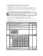
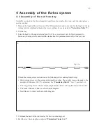
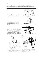
Fig. 4.2.e
Fig. 4.2.f
7.
8.
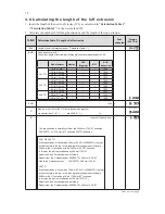
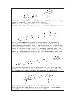
Fig. 4.2.g
9.
Insert the locking pin together with the locking fluid. Secure the pin with a piece of adhesive tape.
(The tape is removed when the lower bearing assembly is slid on.)
NOTE: Do not allow locking adhesive to come into contact with the skin!
Fit a slotted distance tube on the rod forestay and push it into the 2400 mm (94 1/2") luff extrusion.
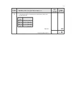
Fig. 4.2.d
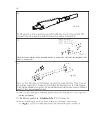
6.
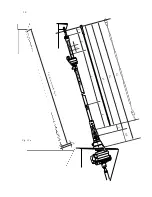
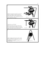
Release the lowest joining sleeve by the upper end terminal and secure the remaining sleeves
again. Slide the next 2400 mm (94 1/2") extrusion over the rod’s top, then fit the joining sleeve and
connecting plate into it’s lower end. Connect this to the lower extrusions. Fit a distance tube onto
the rod and push it into the 2400 mm (94 1/2") extrusion. Release the next joining sleeve, and push
the distance tube from the top until the lower joining sleeve touches the distance tube below the
join. (A spare joining sleeve can be used as an aid.) Check that the distance (J) between the end of
the distance tube and the end of the extrusion is approximately half the length of a joining sleeve.
Connect the remaining extrusions in the same manner.
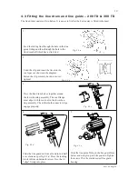
Fit the uppermost, cut distance tube. Release the next joining sleeve, and push the distance tube
from the top until the lower joining sleeve touches the distance tube below the join. The top edge
of the top distance tube should now be roughly flush with the top edge of the extrusion.
Fit the halyard swivel over the top end of the extrusion. Slide it down as far as the sail feeder and
secure it in this position with adhesive tape. Fit the top guard and secure it with the two pre-fitted
screws. Tighten the screws until they bottom, but do not over-tighten.

