background image

75

User Manual

5. FISH FINDER

TM5ce/TM5ci/TM7ce/TM7ci

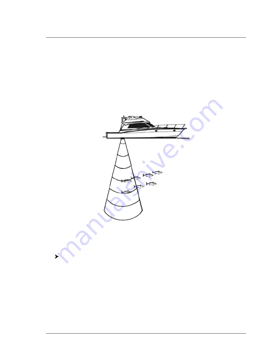
The Fish Finder consists of a high power transmitter, sensitive receiver and a

transducer. The Fish Finder sends an electrical pulse to the transducer which

contains an element that converts the pulse into acoustic (sound) wave which is

sent through the water. As this wave travels from the transducer to the bottom, it

may strike fish, structures, thermoclines (temperature changes in the water).

When the wave strikes an object(s) a certain amount of the wave is reflected back

to the transducer depending on the composition and shape of the object. When

the reflected wave is returned to the transducer it is converted into a voltage and

is amplified by the receiver, processed and sent to the display. The speed of sound

in water is roughly 4800 ft./sec, so  the time lapse between the transmitted signal

and the received echo can be measured and the distance to the object determined.

Fig. 5 - Fish Finder  working principle

5.1

SETTING THE INTERNAL FISH FINDER ON

The internal Fish Finder driver is connected directly to the dedicated serial Port2.

To switch the internal Fish Finder transmission On follow the procedure:

[MENU] + "Advanced Options" + [ENTER] + "Input/Output" + [ENTER] +

"FF Transmission" + [ENTER] + "On" + [ENTER]

NOTE

It is not possible to connect any external Fish Finder unit to the chart plotter.

5.2

UNDERSTANDING THE FISH FINDER PAGE

The display on chart plotters shows a history of time of the echoes received by

the transducer. The chart plotters have a menu that allows adjustments to re-

ceiver sensitivity, depth range and scrolling speed of the Fish Finder display.

Содержание Techmarine

Страница 1: ...T 55 05 7 Sunlight Readable Wide Color Display S4xgTM7wc Internal GPS Receiver TM7e 7 Sunlight Readable WVGA Color Display S4x2TM8wc_qd External Smart GPS Receiver TM7i 7 Sunlight Readable WVGA Color Display S4x2TM8wc_qd Internal GPS Receiver TM7ce 7 Sunlight Readable WVGA Color Display S4x2TM8wc_qd External Smart GPS Receiver Internal FF TM7ci 7 Sunlight Readable WVGA Color Display S4x2TM8wc_qd I...

Страница 2: ... 2010 Seiwa Hong Kong All rights reserved No part of this publication may be reproduced or distributed in any form or by any means or stored in a database or retrieval system without prior written permission of the publisher ...

Страница 3: ...UAGE 22 1 6 SELECTING THE CHART LANGUAGE 23 1 7 C MAP BY JEPPESEN MAX CARTOGRAPHY INFORMATION 23 Data Features 23 Presentation Features 24 Cartographic Data related Features 24 1 8 USING C MAP BY JEPPESEN DATA MEDIA 24 1 9 SIMULATION MODE 24 1 10 CONTROLLING THE DISPLAY 25 Changing Display Mode 25 Moving around the Chart and Changing Chart Scale 28 Finding Your Boat Position 28 Selecting Screen Am...

Страница 4: ...isplaying Track 37 Activating Deactivating Track Recording 37 Clearing Track 37 Selecting Track Number 37 TRACK TO ROUTE FUNCTION 37 Track To Route 37 Select Track Number 38 Select Route Number 38 2 5 DATA WINDOW CUSTOMIZATION ON CHART PAGE 38 2 6 INFO 38 Setting Automatic Info 38 Selecting Automatic Info 38 Displaying Expanded Info page Full Info 39 Info on objects with Pictures 39 Info Tree and ...

Страница 5: ... OPTIONS MENU 49 3 2 MAP OPTIONS MENU 49 Zoom Type 49 Fonts Symbols 49 Perspective View 50 Dynamic Nav Aids 50 Map Orientation 50 Mixing Levels 51 Safety Status Bar DSI Data Safety Indicator 51 Palette 52 Satellite Imagery 52 Currents Prediction 52 3 3 OTHER MAP CONFIGURATIONS 53 Display Mode 53 Marine Settings 53 Depth Settings 54 Land Settings 54 Chart Settings 54 Underwater Objects Settings 55 ...

Страница 6: ... 69 Master Chart Plotter 70 Slave Chart Plotter 70 C Link Navigation Data Acquisition and Display 71 Graphical Representation on Map Display 71 Route Data Report 71 4 4 QUICK INFO 73 Route Navigation Quick Info on the Destination 73 Quick info on Single Destination 73 5 FISH FINDER TM5ce TM5ci TM7ce TM7ci 75 5 1 SETTING THE INTERNAL FISH FINDER ON 75 5 2 UNDERSTANDING THE FISH FINDER PAGE 75 5 2 1...

Страница 7: ...serting the MEDIA 98 Removing the MEDIA 99 CHART PLOTTER DIMENSIONS 99 INSTALLATION AND REMOVING 100 EXTERNAL WIRING 100 TYPICAL CONNECTIONS 101 GPS Connection TM5e External GPS Receiver 101 Autopilot Connection 101 External NMEA Connection 101 External Alarm Connection 102 C COM Connection 102 TM5ce TM5ci 103 FEATURES FUNCTIONS 103 TECHNICAL SPECIFICATIONS 104 FF MODULE 600W 50 200KHz TECHNICAL S...

Страница 8: ...118 TYPICAL CONNECTIONS 118 GPS Connection TM7e External GPS Receiver 118 Autopilot Connection 119 External NMEA Connection 119 C COM Connection 119 TM7ce TM7ci 121 FEATURES FUNCTIONS 121 TECHNICAL SPECIFICATIONS 122 FF MODULE 600W 50 200KHz TECHNICAL SPECIFICATIONS 122 MEDIA INSERTING REMOVING PROCEDURE 123 Inserting the MEDIA 123 Removing the MEDIA 123 CHART PLOTTER DIMENSIONS 123 INSTALLATION A...

Страница 9: ... 142 MEDIA INSERTING REMOVING PROCEDURE 142 Inserting the MEDIA 142 Removing the MEDIA 143 CHART PLOTTER DIMENSIONS 143 INSTALLATION AND REMOVING 143 EXTERNAL WIRING 144 TYPICAL CONNECTIONS 144 GPS Connection 144 Autopilot Connection 145 External NMEA Connection 145 External Alarm Connection 145 C COM Connection 145 T 59 01 147 FEATURES FUNCTIONS 147 TECHNICAL SPECIFICATIONS 148 MEDIA INSERTING RE...

Страница 10: ...12 User Manual ...

Страница 11: ...s enclosed between inverted commas for example MENU Alarms ENTER means press the MENU key using the cursor key select the Alarms menu and then press ENTER Any menu operation and function activation in this User Manual is related to all chart plotter models see the previous table Whenever it is necessary a note has been inserted MANUAL LAYOUT CHAPTER 1 Getting Started Overview of the controls and h...

Страница 12: ...plotter its features and use Installation of the chart plotter T 59 09 Introduction to the basic information on T 59 09 12 chart plotter its features and use Installation of the chart plotter T 59 05 Introduction to the basic information on T 59 05 15 chart plotter its features and use Installation of the chart plotter T 59 01 Introduction to the basic information on T 59 01 controller its feature...

Страница 13: ...LCD displays Avoid overheating which may cause loss of contrast and in extreme cases a darkening of the screen Problems which occur from overheating are re versible when temperature decreases WARNING ON SERIAL PORTS CONNECTION Please be aware that the serial ports are not opto isolated and then the external device is electrically connected to the chart plotter This allows the connection of high sp...

Страница 14: ...16 User Manual ...

Страница 15: ... position CLEAR exits from menu or leaves a menu without making changes if you are not into a menu sets the Navigate Home mode the cursor is centered on ship s position ENTER places Marks Waypoints destination if a specific key is missed and selects many functions for example Find confirms selection MENU selects the main menu when in chart and data page keep it pressed for three seconds to customi...

Страница 16: ...ration their labels for the current functions located on the front panel are shown on the screen right above the keys Also they are used from the chart screen or from the data pages to select one of the data pages available to allow faster access to the page selection When the chart page is selected the soft key labels are not shown By pressing one of the soft keys their labels for the current fun...

Страница 17: ...own for 1 second the numeric key 1 2 3 4 5 it will be possible to assign a different selection to the relative Function Key Move the cursor key up down to place the selector on the desired item move the cursor key to the right or press ENTER to set the selected item move the cursor key to the left or press CLEAR to close the pop up window The possible choices are CHART Chart Chart Display page NAV...

Страница 18: ...en editing a Waypoint see the following picture or when entering menu infor mation insert data by using the visual alphabetical table shown Fig 1 1 6 Example of visual Alphabetical table The table shows all the characters usable Use the cursor key to go through the available characters and select the requested one The soft keys are now activated to Save to save when the entry is complete After pre...

Страница 19: ...ected to a monitor without a different resolution it is possible that the image is not shown So you should set the proper resolution for the monitor in use see the monitor manual and the Par 7 1 7 Switching Off POWER for 3 seconds A countdown timer appears on the screen if you release the key before the countdown timer reaches zero the chart plotter will remain On 1 3 FIRST SETUP PAGE This menu al...

Страница 20: ...peed among Low Medium or High in Chart page or into menu Devices Allows to setup the devices that needs a dedicated port as C Com BBFF 50 200 Radar1 and AIS 38400 Simulation Mode Allows to setup the simulation data before use the Simulation function NOTE1 AVAILABLE FOR T 50 05 T 55 05 TM7e TM7i TM7ce TM7ci TM11 T 59 09 T 59 05 T 59 01 1 4 CHANGING BACKLIGHT AND CONTRAST You can modify the intensit...

Страница 21: ...nt on data If no Local language is available English is used instead NOTE a When User Interface Language is changed Chart Language settings are set as follows MODE is set to Off and Chart Language is set as the User Interface Language selection if available on the chart data otherwise is set to English b If the cartographic data is changed for example the DATA MEDIA is removed or replaced Chart La...

Страница 22: ...dated real time during navigation Smooth Zoom smooth transition of cartographic levels Enhanced Turbo Zoom extra fast cartography level change display ing the most important cartographic objects Enhanced Mixing Levels seamless data presentation Off line redraw cartography level transition without image construction Cartographic Data related Features Guardian Alarm automatic control and alarm over ...

Страница 23: ...mulation Mode ENTER Cursor Control ENTER On ENTER 1 10 CONTROLLING THE DISPLAY This paragraph describes how to change the display mode and how to move around the chart by changing the chart scale Changing Display Mode MENU Page ENTER TM11 T 59 05 DATA T 59 09 PAGE An icons menu1 appears on the screen it shows the available pages NOTE1 NOT AVAILABLE FOR T 59 01 An items menu is shown in place of th...

Страница 24: ...n Distance To Go Fix to Destination Compass Heading Water Temperature Date Time Drift direction Course to steer Steering Electronic bearing line Variable Range Maker Auxiliary Temperature Visual COG Bar Ship Speed relative to the water Radar Speed Through Water Distance the vessel has travelled since the trip log was reset Total distance the vessel has travelled Track status free memory this icon ...

Страница 25: ...27 User Manual Fig 1 10d Example of Navigation Data page Fig 1 10e Example of 3D Road page Fig 1 10f Example of GPS Status page Fig 1 10g Example of Wind Data page1 ...

Страница 26: ...lay as the ship moves To release the cursor from the Home Mode use the cursor key to move the cursor away from the ship s current position Selecting Screen Amplifier In Home mode the Screen Amplifier function sets up the charts on the navigation direction course in order to display more map details in front of the ves sel s position CLEAR MENU Display Options ENTER Screen Amplifier ENTER On ENTER ...

Страница 27: ...Deleting A B Place the cursor on existing A B Clear 1 Deletes the A and B points and the line NOTE1 FOR T 59 09 press 1 Clear 1 13 RANGE BEARING1 FUNCTION The Range Bearing function allows to measure the Lat Lon coordinates between two points on the Chart page NOTE1 FOR T 59 09 T 59 05 The Range and Bearing R B function is called EBL VRM function EBL Electronic Bearing Line is a dot line the origi...

Страница 28: ...eturn to the location use the MOB Man OverBoard function To activate the MOB function a valid GPS fix must be available Inserting MOB MOB If MOB is already placed removes the existing MOB and places a new one Once inserted the system performs the following operations 1 places the MOB icon at ship s position 2 stops navigation to an existing destination if present 3 sets the MOB as destination Sele...

Страница 29: ...int Edit 1 use the cursor key to modify Name Symbol Lat Lon not for Event Color Accept 1 The User Point appears on the selected position with the new symbol and color NOTE To select the User Point presentation MENU Display Options ENTER User Points ENTER There are three possible choices by selecting Off the User Point is not shown on the screen otherwise by selecting On it is shown on the Chart pa...

Страница 30: ... port MENU User Points ENTER Receive ENTER Selecting User Points List page To give information and allow the editing of all stored User Points MENU User Points ENTER List ENTER From this page it is possible the creation of a Route with User Points MENU User Points ENTER List ENTER Route 1 use the cursor key to highlight the Route Select 1 It is possible to link the User Point to the selected Route...

Страница 31: ...e cursor key to insert the notes this is possible only if you have already created a Route Press ENTER to confirm CLR otherwise NOTE1 FOR T 59 09 press 1 Notes Hiding or Showing Route To hide or show the selected Route on the screen MENU Route ENTER Select ENTER use the cursor key to highlight the Route Hide 1 Show 1 NOTE1 FOR T 59 09 press 3 Hide 3 Show Selecting Route Color To select Route legs ...

Страница 32: ...erse 1 The Route is then followed in reverse order with Waypoints renumbered accordingly If the destination is placed on the Route that Route cannot be reversed NOTE1 FOR T 59 09 press 3 Reverse Selecting Route Report page To give information on Waypoints belonging to the selected Route MENU Route ENTER Report ENTER In this page it is possible to modify the Speed and Fuel consumption values MENU R...

Страница 33: ... Automatic Route Check ENTER On ENTER If Automatic Route Check is activated the modified Route legs are checked everytime a Waypoint is added inserted edited or moved Before activating the function you could change the function parameters as the width and the depth of the detected area and the research accuracy To select the width of the detected area aside the Route MENU Route ENTER Route Width E...

Страница 34: ...ure referred to as Tracking can provide invaluable information about the effect of tide and wind influence on the boat s progress as well as giving an indication of the helmsman s performance When full storing capacity has been reached the oldest points are deleted and overwritten by the newest ones Setting up a Track Step Before you use the Track function it is important to specify the Track step...

Страница 35: ...he Track or part of it can be cleared from the screen MENU Track ENTER Delete ENTER T 59 09 T 59 05 TRACK Delete ENTER Begin 1 End 1 and Whole 1 allow to identify the start or the end point of the segment to delete NOTE1 FOR T 59 09 press 1 Begin 2 End and 3 Whole Selecting Track Number The chart plotter has the capability to store up to 5 Tracks To select a Track MENU Track ENTER Config ENTER Act...

Страница 36: ...ds use the cursor key to select data window to customize ENTER use the cursor key to choose selection ENTER Once ENTER is pressed the data type is set The selection window is closed and the Text Area changes according to the selected data type Press CLEAR to exit the edit mode 2 6 INFO Placing the cursor on cartographic objects the information related to the object nearby is shown Setting Automati...

Страница 37: ...ects found has one or more pictures associated there is a camera icon Fig 2 6 Example of Quick Info on objects with picture Press Expand 1 to see the Full Info page there is the small camera icon on a corner of the square containing the object icon or a big photo icon centered on the square for the object without icon NOTE1 FOR T 59 09 press 1 Expand Fig 2 6a Example of Full Info on objects window...

Страница 38: ...page is closed If the information shown on the Lower part of the page exceeds the page size you may scroll the page using Page Dn 1 Use Home 1 to get back to the first page When the selected object is a Tide Station by pressing ENTER the Tide page is shown NOTE1 FOR T 59 09 press 4 Page Dn and 3 Home Quick Info on Lakes Upon viewing the chart of a lake you will click on to query the available info...

Страница 39: ...fo on Lakes Fig 2 6e Example of Full Info page To see the Fishing object press Picture 1 when the Fishing object is high lighted On the screen appears NOTE1 FOR T 59 09 press 1 Picture Fig 2 6f Example of picture associated to the Fishing object 2 7 PORT TIDE INFO Getting Port Info The object Port Marina contains the information about the services available on the selected Port Marina and the area...

Страница 40: ...ic point press Exp All 1 NOTE1 FOR T 59 09 press 1 Expand e 2 Exp All NOTE Port Info icon is visible only if the Ports Services option is On see Par 4 1 Getting Tide Info By placing the cursor over the Tide Station icon Fig 2 7a Tide Info icon By placing the cursor over the Tide Station icon the chart plotter pops up the relative automatic info window and allows displaying a graphical page with th...

Страница 41: ...to the Mean Lower Water value 2 8 FIND FUNCTION The Find function allows searching for the nearest Port Port Services Tide Sta tions Wrecks Obstructions Points Of Interest and Lakes loaded on the DATA MEDIA When the Find function is activated a list of available objects to search is shown Also the Find function allows to center the screen over a selected User Point on the Cursor position or at des...

Страница 42: ...NTER Wrecks ENTER Choose the Wrecks you prefer and press ENTER or Find 1 to locate the se lected Wreck on the map NOTE1 FOR T 59 09 press 1 Find Finding Nearest Obstructions To show the Nearest Obstructions loaded in the DATA MEDIA ENTER Find ENTER Obstructions ENTER Choose the Obstructions you prefer and press ENTER or Find 1 to locate the selected Obstruction on the map NOTE1 FOR T 59 09 press 1...

Страница 43: ...art plotter provides alarms for various functions You can enter the desired alarm range for each function Auto Off To set the automatic shutdown of the alarms when the alarm condition disappears MENU Alarms ENTER Auto Off ENTER Arrival Alarm To set an acoustic alarm to sound when the vessel is approaching the destination MENU Alarms ENTER Arrival Alarm ENTER XTE Alarm To set an acoustic alarm to s...

Страница 44: ...r to navigation such as shallow water depth areas intertidal areas land rocks obstructions and shoreline constructions The maps are scanned every 10 seconds If any of the above objects are found the chart plotter notifies the danger on a dedicated warning message box The active Grounding Alarms are shown in the Grounding Alarm Report page To activate the Grounding Alarm MENU Alarms ENTER Grounding...

Страница 45: ...MEDIA you must format it first This operation prepares the USER MEDIA to receive and store information MENU Save Load ENTER Media 1 Format 1 NOTE1 FOR T 59 09 press 4 SD Card and 3 Format NOTE When a USER MEDIA is formatted all data saved on it will be deleted Saving File on USER MEDIA MENU Save Load ENTER Save 1 select the file type to be added by using related soft key insert the file name and t...

Страница 46: ...t plotter memory they are non duplicated It is re quired to insert the number of the Route Track on which loading data if the Route Track is not empty it is overwritten Deleting File from USER MEDIA To remove files MENU Save Load ENTER Delete 1 NOTE1 FOR T 59 09 press 3 Delete NOTE Remember that this option permanently erases the file T 59 09 T 59 05 Selecting Slot To select the preferred slot whe...

Страница 47: ...TERNATIONAL Draws Nav Aids using international symbology When selected it affects Lights Signals Buoys Beacons display Keypad Beep Enables or disables the single audio beeps emitted any time the chart plotter keypad is pressed If the incorrect key is pressed or the function required cannot be executed the chart plotter emits three beeps Cursor Speed Selects the Cursor Speed among Low Medium or Hig...

Страница 48: ...ng period and color of each Nav aid is read from the Nav Aid attributes available on the data cartridge When the ship is inside the Nav Aid nominal range the light of the Nav Aid will start blinking NOTE When Dynamic Nav Aids option is set to On when the flashing light is Off or when fix position is out of the sector the light color is displayed by using a faint light color Map Orientation MENU Ma...

Страница 49: ...n Off The Safety Status Bar is not shown Icon The Safety Status Bar is not shown but a Warning alarm Icon is shown on the corner of the map screen as soon as any item controlled by the DSI Data Safety Indicator function returns an alarm condition The Warning Icon remains displayed until the alarm condition persists Placing the cursor over this Icon a quick help message is shown next to the Icon al...

Страница 50: ...he chart plotter is not exposed to the direct sunlight When this mode is set the maps are displayed in order to use colors as similar as possible to the ones used in the original paper charts Sunlight It is designed to enhance the visibility of the screen when the chart plotter is exposed to the sunlight The maps are much brighter than in the other modes and the depth areas are filled with white c...

Страница 51: ...t 10 Mt 10 Mt 10 Mt Rocks Icon Depth Icon Icon Icon Icon Icon Obstructions Icon Depth Icon Icon Icon Icon Icon Diffusers Icon Depth Icon Icon Icon Icon Icon Wrecks Icon Depth Icon Icon Icon Icon Icon Marine Settings To control the display on the map of the marine features Place Names Sets On Off the displaying of the Names local area names Name Tags Sets On Off the displaying of a tag for particul...

Страница 52: ...es Sets On Off the displaying of the Chart Boundaries which represents the boundaries of the charts available on the chart plotter Selecting Auto instead if we are in background charts only the first chart levels contained in the DATA MEDIA are displayed if we are in a charts level contained in the DATA MEDIA the next four charts level are displayed Value Added Data SetsOn OffthedisplayingoftheVal...

Страница 53: ... direction in which the Vessel is heading The Course Line origin is the vessel s position so the time lie movement is synchronized with the vessels Icon Course Line course is given by the value of COG Course Over Ground and its length is proportional to the SOG Speed Over Ground Ship Icon Mode SetstheShipIconModebetweenSteadyorBlinking WhenShipIconModeisBlinking theShip Icon and the heading line b...

Страница 54: ...laced Video 2 Shows the image from the video camera 2 on a rectangular window by moving the cursor keys you could select where this window is placed NOTE1 FOR TM7e TM7i TM7ce TM7ci itisavailableonlyonevideocamera soafterselecting Add Video the screen shows the image from the video camera on a window TM7e TM7i TM7ce TM7ci TM11 T 59 09 T 59 05 3 5 2 Video Input menu TM11 T 59 05 DATA Video Input ENT...

Страница 55: ... will be used by the GPS between WAAS and RTCM beacon correction Navigation Speed Sets the Navigation Speed among Low Speed Medium Speed and High Speed NOTE1 AVAILABLE FOR TM5i TM5ci T 55 05 TM7i TM7ci TM5ce TM5ci TM7ce TM7ci Fish Finder Transmission The internal Fish Finder is connected directly to the Port 2 To switch the internal Fish Finder transmission On Off follow the procedure MENU Advance...

Страница 56: ...rt of sentence in a NMEA 0183 sentence that identifies the type of instrument that sends the string The chart plotter allows selecting one of the following Talker identifier II Inte grated Instrument GP GPS EC Electronic Chart System ECS RA Radar and or Radar Plotting SD Sounder Depth The selected Talker ID is applied to all sentences sent by the chart plotter from all Ports To select the Talker I...

Страница 57: ...nabled the ship s position is not changed Compute Correction Corrects fixes from the positioning instrument By placing the cursor on the ship s real position and selecting this option the error is calculated and internally memorized for appropriate correction but not applied Correction Offset Manual correction of fix position Static Navigation1 Sets up a threshold for the speed When the speed rece...

Страница 58: ...out the Targets is being received by AIS Receiver and displayed on the screen CPA Closest Point of Approach is the closest distance that will be achieved be tween your vessel and the tracked Target based on your vessel s speed and direction and the Target s speed and direction CPA Limit This is the distance from your vessel that a Target may reach before a Target is deemed a threat CPA Alarm Occur...

Страница 59: ...reen This information is updated every 3 seconds to 6 minutes depending on speed and rate of turn enabling the track of the vessels in range to be plotted Fig 3 7 1 AIS Symbols 3 7 2 To set the chart plotter for receiving AIS Make sure that the AIS receiver is properly connected to the chart plotter The chart plotter reads the AIS NMEA message VMD type 1 2 3 and 5 Select the used serial port and t...

Страница 60: ...owing information is displayed Vessel Name MMSI number Radio Call Sign SOG COG CPA and TCPA values NOTE The selected AIS Target icon is surrounded by a square frame when user places the cursor over the icon 3 8 C WEATHER SERVICE C Weather Service is an innovative meteorological forecasting system with the ability to visualize the weather forecast overlaying it on cartography The weather data is he...

Страница 61: ...he weather download a squared grey area where the weather data will be downloaded is centered on cursor position See the following picture Fig 3 8 1 Download Area Press Load 1 to activate the C Weather Download the whole data package see the previous Weather data package table are downloaded At the end of the operation press Exit 1 to close the window NOTE1 FOR T 59 09 press 1 Load or 2 Exit Forec...

Страница 62: ...t a great feature for anyone wanting to know the location of another vessel for example you buddy that is catching fish or finding the location of a person you are cruising with are performed by an external device the DSC VHF radio The chart plotter interfaced with a DSC VHF radio prompts the user to see the GPS position of the vessel in distress and also allows for easy navigation to the vessel T...

Страница 63: ... a route to avoid the obstacles Stay on View Exits the pop up screen and remains on the selected map screen 3 9 2 DSC Log page To select the DSC Log page MENU Page ENTER DSC ENTER select the DSC Log page ENTER TM11 T 59 05 DATA DSC ENTER select the DSC Log page ENTER T 59 09 PAGE DSC ENTER select the DSC Log page ENTER Selecting Log shows the Distress Call Log page or Position Request Log page it ...

Страница 64: ...Delete to delete the selected entry press Delete 1 Delete All to delete all entries in the page press Del All 1 NOTE1 FOR T 59 09 press 1 Edit 2 Add 3 Delete or 4 Del All 3 9 4 Quick Info on DSC Icons Placing the cursor on the Distress Call or Position Request icon the following information is displayed Vessel Name MMSI Number Position Date and Time Distance and Bearing from current vessel s posit...

Страница 65: ...Radar antenna transmitter receiver and necessary electronics The scanner unit is connected to a chart plotter equipped with software capable of displaying the Radar functions To select the Radar menu first select one of the pages related to the Radar MENU Page ENTER Radar ENTER select the desired page ENTER TM11 T 59 05 DATA Radar ENTER select the desired page ENTER T 59 09 PAGE Radar ENTER select...

Страница 66: ...68 User Manual ...

Страница 67: ...ll show the Route Leg com posed by the Destination and the Waypoint after the Destination Next Waypoint and activate the navigation to it Any variation to the current C Link Navigation Data will be transferred from the Master to the Slave The Slave will be provided with a dedicated page to show the C Link Navigation Data received from the Master selected from the Route menu MENU Route ENTER Report...

Страница 68: ... Data received from the NMEA port is ig nored So if the two chart plotters are both operating in Master mode the C Link Navigation Data sent by the other chart plotter never processed Under such condition if the navigation is activated on one of the two chart plot ters a warning message will be shown to notify that the C Link navigation data will be ignored by the other chart plotter SLAVE CHART P...

Страница 69: ... the C Link Navigation Data is received the Slave parses the information received and executes the relative actions depending on its current working status Note When the Navigation to the external Destination is activated the Slave Chart Plotter will show all relevant C Link Navigation Data exactly like when the Destination is not the external one Destination Name DST and BRG to Destination calcul...

Страница 70: ...om ship to the Wpt after the Destination calculated Distance to Dest Next Route Leg length Distance to Last Wpt Distance to travel from ship to the End of the Route calculated Distance to Dest Distance From Dest to last Wpt received from PCMPN 1 TTG To Destination Estimated Time to travel the Distance to Last Wpt calculated using Cruising Speed TTG To Next Wpt Estimated Time to travel the Distance...

Страница 71: ...73 User Manual 4 4 QUICK INFO Route Navigation Quick Info on the Destination Fig 4 4 Quick Info on Destination Quick info on Single Destination Fig 4 4a Quick Info on Single Destination ...

Страница 72: ...74 User Manual ...

Страница 73: ...y the receiver processed and sent to the display The speed of sound in water is roughly 4800 ft sec so the time lapse between the transmitted signal and the received echo can be measured and the distance to the object determined Fig 5 Fish Finder working principle 5 1 SETTING THE INTERNAL FISH FINDER ON The internal Fish Finder driver is connected directly to the dedicated serial Port2 To switch t...

Страница 74: ... the left The correct interpretation of the Echogram allows retrieving useful information about what is under the boat See the following Par 5 2 2 for more information Color Bar Colored scale located on the left side of the screen that shows the colors used in the Echogram to represent the echoes strength The color on the top of the bar represents the maximum sonar strength while the color on the ...

Страница 75: ...asily distinguished into an Echogram are White Line 5 3 Thermoclines 2 4 Surface Clutter Structures Fishes 1 6 Bottom Echo Profile 1 4 3 2 6 5 Fig 5 2 1 The Fish Finder Echogram Fishes Fish are represented as arcs because of the cone angle of the transducer In fact as the boat passes over the fish the leading edge of the cone strikes the fish causing a display pixel to be turned on As the boat pas...

Страница 76: ...ottom Echo Profile Bottom profile recorded by the Fish Finder When the echo sounder is set in auto range mode it is automatically kept in the lower half of the screen Other Elements Large anchoring cables are returned by the echo sounder as very long and narrow arcs on the screen 5 3 DISPLAYING THE FISH FINDER PAGE This section will take you through the frequently used operations and assist you to...

Страница 77: ...election done in the Frequency item see Par 5 6 7 The MENU key Pressing MENU activates the Fish Finder Setup menu see Par 5 6 Pressing MENU subsequent times toggles between the Fish Finder Setup menu and the Functions menu The Cursor key Moving the Cursor key up down adjusts the Variable Depth Marker VDM up or down on the screen The ENTER key Pressing ENTER activates the Sensitivity menu see Par 5...

Страница 78: ...h Marker VDM between the 50 and 200kHz displays Moving the cursor up or down will move the VDM up and down Press CLEAR to hide the VDM The ZOOM IN and ZOOM OUT keys From this page pressing ZOOM IN once changes to Zoom 2X pressing ZOOM IN twice changes to Zoom 4X while pressing ZOOM OUT reverts to Zoom 2X and no zoom 5 3 4 Zoom page To display the zoomed Fish Finder page on the left half of the scr...

Страница 79: ...enu and moves the focus to the Fish Finder if the focus the active window in on the Fish Finder the Fish Finder Setup menu is shown Pressing again MENU opens the Functions menu and moves the focus to the Chart NOTE When focus is on the Chart page all keys work in cartography standard mode TM7ce TM7ci 5 3 6 Fish Finder and Radar pages To display the Radar page on the left half of the screen and the...

Страница 80: ...down as to keep the Bottom Line always visible in the lower half of the screen NOTE Moving the Cursor key up down displays the Variable Depth Marker VDM switching the Fish Finder in Marker Zoom mode 5 4 2 The Marker Zoom The Marker Zoom mode is activated either when the Fish Finder is in Manual Range mode see Par 5 6 3 or the Depth Cursor is displayed on the screen In Marker Zoom mode the Fish Fin...

Страница 81: ...es to the next Range status Manual Bottom Lock and Auto If Manual use the cursor up down to adjust the Depth value by 10Ft time and use the cursor left right to adjust the Shift When in meters the step is 2m and it increases to 10m when the key is pressed for more than 1 second If Bottom Lock use the cursor up down to adjust the Bottom Range value by 10Ft at a time If Auto Range the range value is...

Страница 82: ...n in Manual Range Mode it is possible to set Shift the offset from the surface see Par 5 6 5 and Depth see Par 5 6 4 on which the Fish Finder shall operate When in Auto Range Mode the Fish Finder determines automatically the range as to keep the bottom visible in the lower left of the screen In this mode Shift is always set to 0 In Bottom Lock Mode the Fish Finder automatically tracks the range ar...

Страница 83: ...Allows you to change the color scheme of the Fish Finder display The available colors are Blue Background White Background Black Background Gray Scale and Reversed Gray Scale Scrolling Speed Adjusts the chart scrolling rate Note that the scrolling rate is limited by the sound speed and the depth according with the following relation the deeper the setting the slower the scrolling rate 100 is the m...

Страница 84: ...ed by the unit switches an alarm to sound These options are Off Small Medium Big and Huge The alarm sounds if the set size or bigger is detected 5 6 13 Save Load Menu Insert the USER MEDIA into the slot then follow the procedure MENU Save Load ENTER Load Settings from USER MEDIA Load the complete settings from the USER MEDIA and changes the active menu settings Save Settings to USER MEDIA This is ...

Страница 85: ...ng various time differences between transmitted signals the GPS receiver can determine its present position anywhere on earth and thanks to continuous updates calculate speed and course information 6 1 HOW GPS WORKS Currently the GPS constellation consists of 26 orbiting satellites including 3 spares but this number will increase in the future The GPS receiver computes an accurate position by calc...

Страница 86: ...iameters d1 d2 and d3 6 1 1 Position Fixing Accuracy HDOP The GPS fix accuracy is due to the locations of 3 satellites in the sky High accuracy is obtainable when the satellites are widely scattered in the sky on the contrary accuracy is reduced when the satellites have gathered in a narrow space In the following figure in both cases it is possible to obtain the GPS fix but in the left case the ac...

Страница 87: ...ault values Before this step you have the option of saving user Marks Track history and Routes to a User MEDIA this is an optional purchase from your dealer To confirm to clear RAM press ENTER again but if this time you do not wish to clear RAM press CLEAR 7 1 2 DIM Menu Contrast Each time you press the cursor key to right the screen will decrease contrast when you press the left key the contrast ...

Страница 88: ...n Resolution Sets the resolution among 1024x768 800x600 640x480 default Horizontal Size Allows entering the actual horizontal size of the screen The value can be entered either in centimeters or inches the default is 30 5 cm The unit of measure is user selectable see Screen Size Unit option If the unit of measure is changed the value is converted Screen Size Unit Allows entering the screen size un...

Страница 89: ... Beacons Buoys and Beacons are used to indicate to mariners recommended or estab lished routes underwater dangers restrictions and regulations They can be lighted or not and are colored according to their international code BRG Bearing Angle between the North True or Magnetic and a destination The horizontal direction of one terrestrial point from another referring to the North True or Magnetic It...

Страница 90: ...areas included in the user selectable range of minimum and maximum depth limits The sea area that is beyond the selected range is filled by an uniform white color the sea area that is inside the selected range is filled by ordinary multicolor shading The Spot Soundings and Depth Contours are dis played on the range only Depth Line Also called Bathymetric Line Imaginary line connecting points of eq...

Страница 91: ...ument building silo tower mast on land which can be used in determining a location or a direction Latitude Angular distance North or South of the equator measured by lines encircling the earth parallel to the equator in degrees from 0 to 90 LAT LON Coordinate system using Latitude and Longitude coordinates to define a posi tion on earth Lat Lon Grid Grid of parallels of Latitude and meridians of L...

Страница 92: ...econdary stations of a Loran C chain which are used to calculate the TD Time Difference position of a point in the map area covered by the selected Loran C chain Pictures Diagrams The MAX data format allows assigning one or more image to any cartographic object These Pictures are typically used to facilitate the identification of carto graphic objects or places around the map they can be the lands...

Страница 93: ...of possible positions where the measured Time Difference TD between arrival of pulses from those stations would be observed The TD is measured from the time of reception of the master station signal to the time of reception of the slave station signal see also Pair Tide Periodic rise and fall of the surface of oceans bays etc due principally to the gravitational interactions between the Moon and E...

Страница 94: ...h other DOT or ganizations and DOD is augmenting the GPS SPS with a satellite based aug mentation system the WAAS It will provide a signal in space to WAAS users to support en route through precision approach navigation After achieving initial operational capability the WAAS will then be incrementally improved over the next years to expand the area of coverage increase the availability of precisio...

Страница 95: ...otos Diagrams Automatic Information on all chart objects and User Points Find function for Ports Services Ports By Name Ports By Distance Tide Stations Wrecks Obstructions Lakes Information Lakes By Name Points Of Interest Cursor Coordinates and User Points Positional information from GPS Depth Graph pages Navigation Data page 3D Road page GPS Status page Gauges pages AIS Report List page Fish Fin...

Страница 96: ...EPPESEN DATA MEDIA Operating temperature range 32 to 131 F 0 to 55 C Memory Non volatile Keyboard Silicon rubber backlight Weight with external bracket 600 gr TM5i 550 gr TM5e When the package containing the chart plotter is first opened please check it for the following contents if any parts are missing contact the dealer the chart plot ter was purchased from Bracket and I O cable 1 5 mt 5 9 feet...

Страница 97: ...99 User Manual Removing the MEDIA Remove the front cover and eject the MEDIA you wish to remove out of the slot CHART PLOTTER DIMENSIONS ...

Страница 98: ...e blade between the gasket and the lateral side of the rear to turn the chart plotter Warning Do not pull the gasket during cut operation to avoid compromising the chart plotter watertight seal EXTERNAL WIRING MINI B USB connector RED GREEN BROWN NC NC BLACK YELLOW SHIELD CABLE COLOR 10 35Vdc OUTPUT 3 INPUT 3 GND COMMON FUNCTION 1 2 3 4 5 6 PIN SMART GPS sensor CABLE COLOR BLACK RED WHITE GREEN GR...

Страница 99: ...OWER I O POWER SUPPLY PWR GND COMMON PWR 10 35 Vdc OUTPUT 2 INPUT 2 1 2 5 7 BLACK RED GRAY BROWN POWER I O CABLE POWER I O CABLE PIN CABLE COLOR FUNCTION 1 COMMON RX AUTOPILOT Autopilot Connection on Port 2 External NMEA Connection POWER SUPPLY 1 POWER I O EXTERNAL NMEA DEVICE EXTERNAL NMEA DEVICE COMMON RX TX PWR GND COMMON PWR 10 35 Vdc INPUT 1 COMMON OUTPUT 1 POWER I O CABLE POWER I O CABLE PIN...

Страница 100: ...BLUE 1 2 8 1 Current MAX 300mA POWER SUPPLY POWER I O CONNECTOR CABLE External Alarm Connection C COM Connection POWER I O 1 2 3 4 5 6 7 8 PIN CABLE COLOR FUNCTION BLACK RED WHITE GREEN GRAY YELLOW BROWN BLUE PWR GND COMMON PWR 10 35 Vdc Used by C COM Used by C COM OUTPUT 2 Used by C COM INPUT 2 OUTPUT EXTERNAL ALARM POWER I O CONNECTOR CABLE C COM Connection ...

Страница 101: ...Photos Diagrams Automatic Information on all chart objects and User Points Find function for Ports Services Ports By Name Ports By Distance Tide Stations Wrecks Obstructions Lakes Information Lakes By Name Points Of Interest Cursor Coordinates and User Points Positional information from GPS Depth Graph pages Navigation Data page 3D Road page GPS Status page Gauges pages AIS Report List page Fish F...

Страница 102: ...Memory Non volatile Keyboard Silicon rubber backlight Weight with external bracket 700 gr FF MODULE 600W 50 200KHZ TECHNICAL SPECIFICATIONS Power Output 600W 4800Wpp 50 200KHz Dual Fre quency Max Depth 213m 700Ft at 200kHz 457m 1500Ft at 50kHz Automatic Recognition of the AIRMAR X DUCER ID transducers for best performance Advanced Digital Signal Processing Speed Temperature Sensor if available on ...

Страница 103: ...P BY JEPPESEN label Gently push the MEDIA into the slot push the MEDIA in as far as it will go to hold fixed into the slot and place the front cover again cod e date ser n class A Removing the MEDIA Remove the front cover and eject the MEDIA you wish to remove out of the slot CHART PLOTTER DIMENSIONS 160mm 6 3 195 5mm 7 7 166 6 5 76 5mm 3 101 5mm 4 1 2 7 m m 5 34mm 1 3 19mm 0 7 91mm 3 6 110 5mm 4 ...

Страница 104: ...y remove the silicon gasket between rear and front placed around the chart plotter To remove the gasket lay the chart plotter on its front side to pay attention do not damage LCD and keyboard and use a sharpening blade Put the blade between the gasket and the lateral side of the rear to turn the chart plotter Warning Do not pull the gasket during cut operation to avoid compromising the chart plott...

Страница 105: ...ERNAL NMEA DEVICE EXTERNAL NMEA DEVICE COMMON RX TX PWR GND COMMON PWR 10 35 Vdc INPUT 1 COMMON OUTPUT 1 POWER I O CABLE POWER I O CABLE PIN CABLE COLOR FUNCTION 1 2 3 4 6 BLACK RED WHITE GREEN YELLOW External NMEA Connection on Port 1 External Alarm Connection POWER I O 1 2 8 PIN CABLE COLOR FUNCTION PWR GND COMMON PWR 10 35 Vdc OUTPUT EXTERNAL ALARM Open Collector BLACK RED BLUE 1 2 8 1 Current ...

Страница 106: ...108 User Manual ...

Страница 107: ...rents data Photos Diagrams Automatic Information on all chart objects and User Points Find function for Ports Services Ports By Name Ports By Distance Tide Stations Wrecks Obstructions Lakes Information Lakes By Name Points Of Interest Cursor Coordinates and User Points Positional information from GPS Depth Graph pages Navigation Data page 3D Road page GPS Status page Wind Data page Gauges pages D...

Страница 108: ... LCD active area 7 Display Resolution 480 x 234 pixels MEDIA C Card Cartography C MAP BY JEPPESEN DATA MEDIA Operating temperature range 32 to 131 F 0 to 55 C Memory Non volatile Keyboard Silicon rubber backlight Weight 1 1 Kg When the package containing the chart plotter is first opened please check it for the following contents if any parts are missing contact the dealer the chart plot ter was p...

Страница 109: ...To make the Flush Deck installation it is necessary to permanently remove the silicon gasket between rear and front placed around the chart plotter To remove the gasket lay the chart plotter on its front side to pay attention do not damage LCD and keyboard and use a sharpening blade Put the blade between the gasket and the lateral side of the rear to turn the chart plotter Warning Do not pull the ...

Страница 110: ...0 35Vdc INPUT 1 COMMON OUTPUT 1 INPUT 2 OUTPUT 2 RTCM 104 INPUT OUTPUT 3 COMMON TYPICAL CONNECTIONS GPS Connection T 50 05 External GPS Receiver QUICK DISCONNECT BRACKET CABLE DESCRIPTION WIRE COLOR BLACK RED WHITE GREEN YELLOW BROWN GRAY ORANGE PINK BLUE PWR GND COMMON POWER 10 35Vdc INPUT 1 COMMON OUTPUT 1 INPUT 2 OUTPUT 2 INPUT 3 OUTPUT 3 COMMON POWER SUPPLY SMART GPS SENSOR GPS POWER SWITCH DI...

Страница 111: ...83 OUTPUT NMEA0183 INPUT SIGNAL RETURN NMEA0183 DEVICE FUNCTION BLACK RED WHITE GREEN YELLOW BROWN GRAY ORANGE PINK BLUE PWR GND COMMON POWER 10 35Vdc INPUT 1 COMMON OUTPUT 1 INPUT 2 OUTPUT 2 INPUT 3 OUTPUT 3 COMMON QUICK DISCONNECT BRACKET CABLE DESCRIPTION WIRE COLOR External NMEA Connection on Port 1 C COM Connection To connect the modem C COM to the chart plotter with quick disconnect bracket ...

Страница 112: ...X C COM RX FUNCTION Connection for the Port 1 Beacon Receiver Connection T 55 05 Internal GPS Receiver RTCM 104 OUTPUT SIGNAL RETURN DIFFERENTIAL BEACON RECEIVER BLACK RED WHITE GREEN YELLOW BROWN GRAY ORANGE PINK BLUE GND COMMON POWER 10 35Vdc INPUT 1 COMMON OUTPUT 1 INPUT 2 OUTPUT 2 INPUT 3 OUTPUT 3 COMMON QUICK DISCONNECT BRACKET CABLE DESCRIPTION WIRE COLOR FUNCTION NOTE For T 50 05 To connect...

Страница 113: ...data Photos Diagrams Automatic Information on all chart objects and User Points Find function for Ports Services Ports By Name Ports By Distance Tide Stations Wrecks Obstructions Lakes Information Lakes By Name Points Of Interest Cursor Coordinates and User Points Positional information from GPS Depth Graph pages Navigation Data page 3D Road page GPS Status page Wind Data page Gauges page DSC Log ...

Страница 114: ...t Viewable Color LCD active area 7 wide Display Resolution 800 x 480 pixels MEDIA SD Card TM7e TM7i Cartography C MAP BY JEPPESEN DATA MEDIA Operating temperature range 32 to 131 F 0 to 55 C Memory Non volatile Keyboard Silicon rubber backlight Weight 1 2 Kg When the package containing the chart plotter is first opened please check it for the following contents if any parts are missing contact the...

Страница 115: ...To make the Flush Deck installation it is necessary to permanently remove the silicon gasket between rear and front placed around the chart plotter To remove the gasket lay the chart plotter on its front side to pay attention do not damage LCD and keyboard and use a sharpening blade Put the blade between the gasket and the lateral side of the rear to turn the chart plotter Warning Do not pull the ...

Страница 116: ...dc INPUT1 SIGNAL RETURN OUTPUT1 INPUT2 OUTPUT2 INPUT3 OUTPUT3 SIGNAL RETURN FUNCTION Available on chartplotter with GPS EXTERNAL TYPICAL CONNECTIONS GPS Connection TM7e External GPS Receiver DIFFERENTIAL BEACON RECEIVER RTCM 104 OUTPUT SIGNAL RETURN FUNCTION QUICK DISCONNECT BRACKET CABLE DESCRIPTION WIRE COLOR BLACK RED WHITE GREEN YELLOW BROWN GRAY ORANGE PINK BLUE POWER SUPPLY GND POWER SUPPLY ...

Страница 117: ...TE GREEN YELLOW BROWN GRAY ORANGE PINK BLUE POWER SUPPLY GND POWER SUPPLY NMEA0183 C COM SIGNAL RETURN NMEA0183 180 180CDX C COM NMEA0183 C COM NMEA0183 180 180CDX C COM NMEA0183 C COM NMEA0183 180 180CDX C COM SIGNAL RETURN POWER GND POWER 10 35Vdc INPUT1 SIGNAL RETURN OUTPUT1 INPUT2 OUTPUT2 INPUT3 OUTPUT3 SIGNAL RETURN FUNCTION External NMEA Connection on Port 1 C COM Connection To connect the m...

Страница 118: ...ECT BRACKET CABLE DESCRIPTION WIRE COLOR POWER GND POWER 10 35Vdc INPUT 1 SIGNAL RETURN OUTPUT 1 BLACK RED WHITE GREEN YELLOW POWER SUPPLY GND POWER SUPPLY C COM SIGNAL RETURN C COM FUNCTION C COM GSM Plus CABLE WIRE COLOR FUNCTION GND POWER SUPPLY C COM TX C COM TX C COM RX BLACK RED WHITE GREEN YELLOW Connection for the Port 1 ...

Страница 119: ...nformation database Tides Currents data Photos Diagrams Automatic Information on all chart objects and User Points Find function for Ports Services Ports By Name Ports By Distance Tide Stations Wrecks Obstructions Lakes Information Lakes By Name Points Of Interest Cursor Coordinates and User Points Positional information from GPS Depth Graph pages Navigation Data page 3D Road page GPS Status page ...

Страница 120: ...de Display Resolution 800 x 480 pixels MEDIA SD Card TM7ce TM7ci Cartography C MAP BY JEPPESEN DATA MEDIA Operating temperature range 32 to 131 F 0 to 55 C Memory Non volatile Keyboard Silicon rubber backlight Weight 1 2 Kg FF MODULE 600W 50 200KHZ TECHNICAL SPECIFICATIONS Power Output 600W 4800Wpp 50 200KHz Dual Fre quency Max Depth 213m 700Ft at 200kHz 457m 1500Ft at 50kHz Automatic Recognition ...

Страница 121: ... T 50 06 FF TM7ce MEDIA INSERTING REMOVING PROCEDURE Inserting the MEDIA Open the door hold the MEDIA by the short side so that you can see the C MAP BY JEPPESEN label gently push the MEDIA into the door slot and close the door Removing the MEDIA To remove the MEDIA open the door then remove the CARD from the slot CHART PLOTTER DIMENSIONS ...

Страница 122: ...rmanently remove the silicon gasket between rear and front placed around the chart plotter To remove the gasket lay the chart plotter on its front side to pay attention do not damage LCD and keyboard and use a sharpening blade Put the blade between the gasket and the lateral side of the rear to turn the chart plotter Warning Do not pull the gasket during cut operation to avoid compromising the cha...

Страница 123: ...125 User Manual EXTERNAL WIRING External Wiring TM7ce External GPS Receiver External Wiring TM7ci Internal GPS Receiver ...

Страница 124: ...6 User Manual TYPICAL CONNECTIONS GPS Connection TM7ce External GPS Receiver GPS Connection on Port 3 Autopilot Connection Autopilot Connection on Port 1 for TM7ce Autopilot Connection on Port 1 for TM7ci ...

Страница 125: ...ion QUICK DISCONNECT BRACKET CABLE DESCRIPTION WIRE COLOR BLACK RED WHITE GREEN YELLOW POWER SUPPLY GND POWER SUPPLY C COM SIGNAL RETURN C COM POWER GND POWER 10 35Vdc INPUT1 SIGNAL RETURN OUTPUT1 FUNCTION C COM GSM Plus CABLE WIRE COLOR BLACK RED WHITE GREEN YELLOW GND POWER SUPPLY C COM TX C COM TX C COM RX FUNCTION C COM Connection on Port 1 ...

Страница 126: ...128 User Manual ...

Страница 127: ...ase Tides Currents data Photos Diagrams Automatic Information on all chart objects and User Points Find function for Ports Services Ports By Name Ports By Distance Tide Stations Wrecks Obstructions Lakes Information Lakes By Name Points Of Interest Cursor Coordinates and User Points Positional information from GPS Depth Graph pages Navigation Data page 3D Road page GPS Status page Wind Data page G...

Страница 128: ...A 0183 Autopilot Interface NMEA 0180 NMEA 0180 CDX NMEA 0183 Video Input PAL or NTSC video signals au tomatically selected Video Output VGA compatible adapter cable Display Sun Light Viewable Color Transflective LCD active area 10 4 Display Resolution 800 x 600 pixels MEDIA SD Card TM11 Cartography C MAP BY JEPPESEN DATA MEDIA Operating temperature range 32 to 131 F 0 to 55 C Memory Non volatile K...

Страница 129: ... MEDIA by the short side gently push the MEDIA into the door slot and close the door Removing the MEDIA To remove the MEDIA open the door then remove the MEDIA from the slot CHART PLOTTER DIMENSIONS INSTALLATION AND REMOVING Example of left Flush deck installation and right Bracket installation ...

Страница 130: ...LLOW SHIELD WIRE COLOR FUNCTION SMART GPS SENSOR 1 GND 2 VCC 3 R 4 G 5 B 6 HSYNC 7 VSYNC 8 N C 9 BRIGHT CONTROL PIN FUNCTION BLACK RED WHITE GREEN GRAY YELLOW BROWN BLUE PIN 1 2 3 4 5 6 7 8 WIRE COLOR FUNCTION GND COMMON POWER INPUT 10 35 Vdc INPUT 1 COMMON OUTPUT 2 OUTPUT 1 INPUT 2 EXTERNAL ALARM OUTPUT GND COMMON POWER OUTPUT INPUT 4 COMMON OUTPUT 5 OUTPUT 4 INPUT 5 EXTERNAL ALARM OUTPUT 10 35 V...

Страница 131: ...K RED GRAY BROWN PIN 1 2 5 7 WIRE COLOR FUNCTION AUTOPILOT COMMON RX Autopilot on Port 2 External NMEA Connection EXTERNAL NMEA DEVICE POWER I O POWER SUPPLY 1 POWER I O CABLE POWER I O CABLE PWR GND COMMON POWER INPUT 10 35 Vdc INPUT 1 COMMON OUTPUT 1 BLACK RED WHITE GREEN YELLOW PIN 1 2 3 4 6 WIRE COLOR FUNCTION COMMON TX RX External NMEA on Port 1 POWER I O POWER SUPPLY 1 POWER I O CABLE POWER ...

Страница 132: ...BLUE 1 2 8 1 Current MAX 300mA POWER SUPPLY POWER I O CONNECTOR CABLE External Alarm Connection C COM Connection POWER I O 1 2 3 4 5 6 7 8 PIN CABLE COLOR FUNCTION BLACK RED WHITE GREEN GRAY YELLOW BROWN BLUE PWR GND COMMON PWR 10 35 Vdc Used by C COM Used by C COM OUTPUT 2 Used by C COM INPUT 2 OUTPUT EXTERNAL ALARM POWER I O CONNECTOR CABLE C COM Connection ...

Страница 133: ...formation on all chart objects and User Points Find function for Ports Services Ports By Name Ports By Distance Tide Stations Wrecks Obstructions Lakes Information Lakes By Name Points Of Interest Cursor Coordinates and User Points Positional information from GPS Depth Graph pages Navigation Data page 3D Road page GPS Status page Gauges page DSC Log and DSC Directory pages AIS Report List page Fis...

Страница 134: ...splay Resolution 800 x 600 pixels MEDIA C Card Cartography C MAP BY JEPPESEN DATA MEDIA Auxiliary Memory SD Card 16 MB or more Operating temperature range 32 131 F 0 55 C Memory Non volatile with battery back up Keyboard Silicon rubber backlight Weight 7 8 Kg When the package containing the chart plotter is opened for the first time after purchase please make sure that the following contents are p...

Страница 135: ...rtography information will be displayed when you move the cursor into an area covered by the new charts making pan or zoom operations The boundary of each chart digitized in the current MEDIA is shown as a rectangle Removing the MEDIA Press lightly the MEDIA you wish to remove 1 and move it up 2 until you hear a click the MEDIA will ejected out of the slot 3 CHART PLOTTER DIMENSIONS 45 3 1 8 184 3...

Страница 136: ... Alarm Connection GPS Connection SMART GPS SENSOR GPS SENSOR CABLE GPS SENSOR CABLE POWER OUTPUT 10 35 Vdc GPS RX GPS TX GND COMMON RED GREEN BROWN BLACK YELLOW SHIELD PIN 1 2 3 6 GPS ANTENNA 1 2 3 4 5 6 WIRE COLOR FUNCTION AUX IN I O Connector and External NMEA Connection Video Input Connector ...

Страница 137: ...139 User Manual Video Output Connector C COM Connection ...

Страница 138: ...140 User Manual ...

Страница 139: ...cts and User Points Find function for Ports Services Ports By Name Ports By Distance Tide Stations Wrecks Obstructions Lakes Information Lakes By Name Points Of Interest Cursor Coordinates and User Points Positional information from GPS Depth Graph pages Navigation Data page 3D Road page GPS Status page Gauges page DSC Log and DSC Directory pages AIS Report List page Fish Finder Radar Video Input ...

Страница 140: ...tomati cally selected Video Output VGA compatible adapter cable Display TFT transmissive LCD active area 15 Display Resolution 1024 x 768 pixels MEDIA C Card Cartography C MAP BY JEPPESEN DATA MEDIA Operating temperature range 32 to 131 F 0 to 55 C Memory Internal non volatile for user data backup Keyboard Silicon rubber backlight Weight 4 5 Kg When the package containing the chart plotter is firs...

Страница 141: ... User Manual in as far as it will go then close the door to hold fixed into the slot Removing the MEDIA Open the door and remove the MEDIA out of the slot CHART PLOTTER DIMENSIONS INSTALLATION AND REMOVING ...

Страница 142: ...BROWN NC NC BLACK YELLOW SHIELD WIRE COLOR FUNCTION GND NC RED GREEN BLUE HSYNC VSYNC 5V OUT BRIGHTNESS PIN 1 2 3 4 5 6 7 8 9 FUNCTION PWR GND COMMON PWR OUTPUT 12 35 Vdc INPUT 1 COMMON OUTPUT 2 OUTPUT 1 INPUT 2 EXT ALARM OUTPUT 1 PIN 1 2 3 4 5 6 7 8 BLACK RED WHITE GREEN GRAY YELLOW BROWN BLUE WIRE COLOR FUNCTION GPS PORT 3 CONNECTOR CABLE I O PORT 4 5 CONNECTOR CABLE VIDEO INPUT CONNECTOR VIDEO ...

Страница 143: ...VICE PWR GND COMMON INPUT 1 INPUT 1 OUTPUT 1 BLACK WHITE GREEN YELLOW PIN 1 3 4 6 WIRE COLOR FUNCTION I O PORT 1 2 CABLE I O PORT 1 2 CABLE External NMEA on Port 1 External Alarm Connection External Alarm Connection C COM Connection POWER I O 1 2 3 4 5 6 7 8 PIN CABLE COLOR FUNCTION BLACK RED WHITE GREEN GRAY YELLOW BROWN BLUE PWR GND COMMON PWR 12 35 Vdc Used by C COM Used by C COM OUTPUT 2 Used ...

Страница 144: ...146 User Manual ...

Страница 145: ...Distance Tide Stations Wrecks Obstructions Lakes Information Lakes By Name Points Of Interest Cursor Coordinates and User Points Positional information from GPS Depth Graph pages Navigation Data page 3D Road page GPS Status page Wind Data page Gauges page DSC Log and DSC Directory pages AIS Report List page Fish Finder Radar pages1 10000 User Points Waypoints Events Marks Dynamic handling of User ...

Страница 146: ...A compatible adapter cable Cartography C MAP BY JEPPESEN DATA MEDIA Operating temperature range 32 to 131 F 0 to 55 C Memory Non volatile with battery back up Keyboard Silicon rubber backlight Weight 950 gr When the package containing the controller is first opened please check it for the following contents if any parts are missing contact the dealer the controller was purchased from External brac...

Страница 147: ...ish to remove out of the slot CONTROLLER DIMENSIONS INSTALLATION AND REMOVING Warning In order to protect the chart plotter video board please make sure that the power cables of the monitor and of the chart plotter are physically separated with protection against electrical discharge ...

Страница 148: ...L WIRING SMART GPS SENSOR USB Port BLACK RED WHITE GREEN GRAY YELLOW BROWN BLUE PIN 1 2 3 4 5 6 7 8 WIRE COLOR FUNCTION GND COMMON POWER INPUT 10 35 Vdc INPUT 1 COMMON OUTPUT 2 OUTPUT 1 INPUT 2 EXTERNAL ALARM OUTPUT GND COMMON POWER OUTPUT 10 35 Vdc INPUT 4 COMMON OUTPUT 5 OUTPUT 4 INPUT 5 EXTERNAL ALARM OUTPUT BLACK RED WHITE GREEN GRAY YELLOW BROWN BLUE PIN 1 2 3 4 5 6 7 8 WIRE COLOR FUNCTION PI...

Страница 149: ...dc INPUT 1 COMMON OUTPUT 1 BLACK RED WHITE GREEN YELLOW PIN 1 2 3 4 6 WIRE COLOR FUNCTION COMMON TX RX Autopilot on Port 1 POWER I O POWER SUPPLY 1 POWER I O CABLE POWER I O CABLE PWR GND COMMON POWER INPUT 10 35 Vdc OUTPUT 2 INPUT 2 BLACK RED GRAY BROWN PIN 1 2 5 7 WIRE COLOR FUNCTION AUTOPILOT COMMON RX Autopilot on Port 2 External NMEA Connection EXTERNAL NMEA DEVICE POWER I O POWER SUPPLY 1 PO...

Страница 150: ...I O 1 2 8 PIN CABLE COLOR FUNCTION PWR GND COMMON PWR 10 35 Vdc OUTPUT EXTERNAL ALARM Open Collector BLACK RED BLUE 1 2 8 1 Current MAX 300mA POWER SUPPLY POWER I O CONNECTOR CABLE External Alarm Connection C COM Connection POWER I O 1 2 3 4 5 6 7 8 PIN CABLE COLOR FUNCTION BLACK RED WHITE GREEN GRAY YELLOW BROWN BLUE PWR GND COMMON PWR 10 35 Vdc Used by C COM Used by C COM OUTPUT 2 Used by C COM ...

Страница 151: ...stry standard thread used on a wide range of mounting brackets including the swivel joints commonly used for angled surfaces However due to the manufacturing process of these mounting brackets you may see that there is some slop when tightening down the antenna to the bracket This is of no concern however as the antenna must be tightened until the antenna stops rotating on the antenna mounting bra...

Страница 152: ...e cable go through the central hole 4 Apply a small coat of RTV to the underside of the antenna 5 Place the antenna and then screw it with the three M3 screws Installing GPS Antenna III DIMENSIONS 60mm 2 63 41mm 1 61 98mm 3 86 GPS Antenna Dimensions ...

Страница 153: ...uth 91 B backlight 17 22 Bathymetric 23 Beacon 91 Beacon Receiver Connection 114 Bearing 59 BOD 58 Bottom Echo Profile 78 Bottom Lock Zoom 82 Bottom Range 84 BRG Bearing 91 Brightness 89 Buoy 91 BWC 58 C C Card 98 104 110 116 122 130 136 142 148 C COM 58 C COM Connection 139 C COM GSM PLUS Connection 134 145 152 C COM GSM Plus Connection 58 102 107 119 C Link 69 70 C Link menu 59 C Weather Service...

Страница 154: ...Diffusers 35 53 55 Digital Depth 76 DIM Menu 89 Display AIS 61 Display Mode 53 Display Mode Track 37 Display Options 55 Display Settings 90 Display Setup Menu 85 Displaying Track 37 Distance Step Track 36 Distance Unit 22 49 Distress Call 64 Download 63 Download Area 63 DPT Depth from Transducer 92 Dredged Areas 35 DSC 64 DSC Directory page 65 DSC Icons 66 DSC Log page 65 DSI 51 DST Distance 92 Du...

Страница 155: ...112 118 126 132 138 144 151 GPS constellation 87 GPS position calculation 88 GPS Setup Menu 57 GPS STATUS 19 GPS Status page 19 27 Grounding Alarm 46 Grounding Alarm Range 46 Grounding Alarm Report 46 Guardian Alarm 24 Guardian Technology 52 H HDG 58 HDG Heading 93 HDOP 46 88 93 HDOP Alarm 46 Head Up 50 Heading Simulation 25 Heading Alarm 46 Hiding Route 33 High Water Temp 86 Home mode 17 93 Horiz...

Страница 156: ...ette 52 North Up 50 Numeric Keys 17 18 O Object Info 24 Obstructions 35 44 53 55 Off line redraw 24 Official data source 23 Operating Frequency 77 OSGB 94 Other Map Configurations 53 Over Zoom 24 P Page 25 Page Selection menu 25 78 Pair 94 Palette 52 Perspective View 24 50 Photos Diagrams 24 Pictures 39 Pictures Diagrams 94 Pingos 35 Place Names 53 POI 53 54 Points Of Interest 45 Port By Distance ...

Страница 157: ...25 Sleeping Target 61 Smart GPS External 153 Smooth Zoom 24 SNR 95 soft keys 79 83 Software Keys 18 Software Keys Customization 19 SOG 95 Sorting directory 48 Speed Simulation 25 Speed Filter 59 Speed Unit 22 49 Spot Soundings 23 95 Static Navigation 59 Status 19 STC 85 STC Length 85 STC Soft Key 83 STC Strenth 85 Step Unit Track 36 stop the navigation 36 STR Steering 95 Structures 78 STW Speed Th...

Страница 158: ... 77 Variation 96 VDM 77 Video 20 Video 1 20 56 Video 2 20 56 Video Input Connector 138 Video Input menu 56 VIDEO MODE 56 Video Output Connector 139 VIDEOCAMERA 20 VIDEOCAMERA 1 20 VIDEOCAMERA 2 20 visual alphabetical table 20 Visual COG Bar 56 VMG 96 voltage 21 VRM 18 VTG 58 W WAAS 96 WARNING 15 Warning Message 76 Water Temp Rate 86 Water Temperature 76 85 WAYPOINT 20 Waypoint 17 20 31 96 Waypoint...

Отзывы: