Smart Positioner
SP740 Series
8. Auto Calibration & PCB Operation
8.1 Warning
after saparating valve and actuator in system completely.
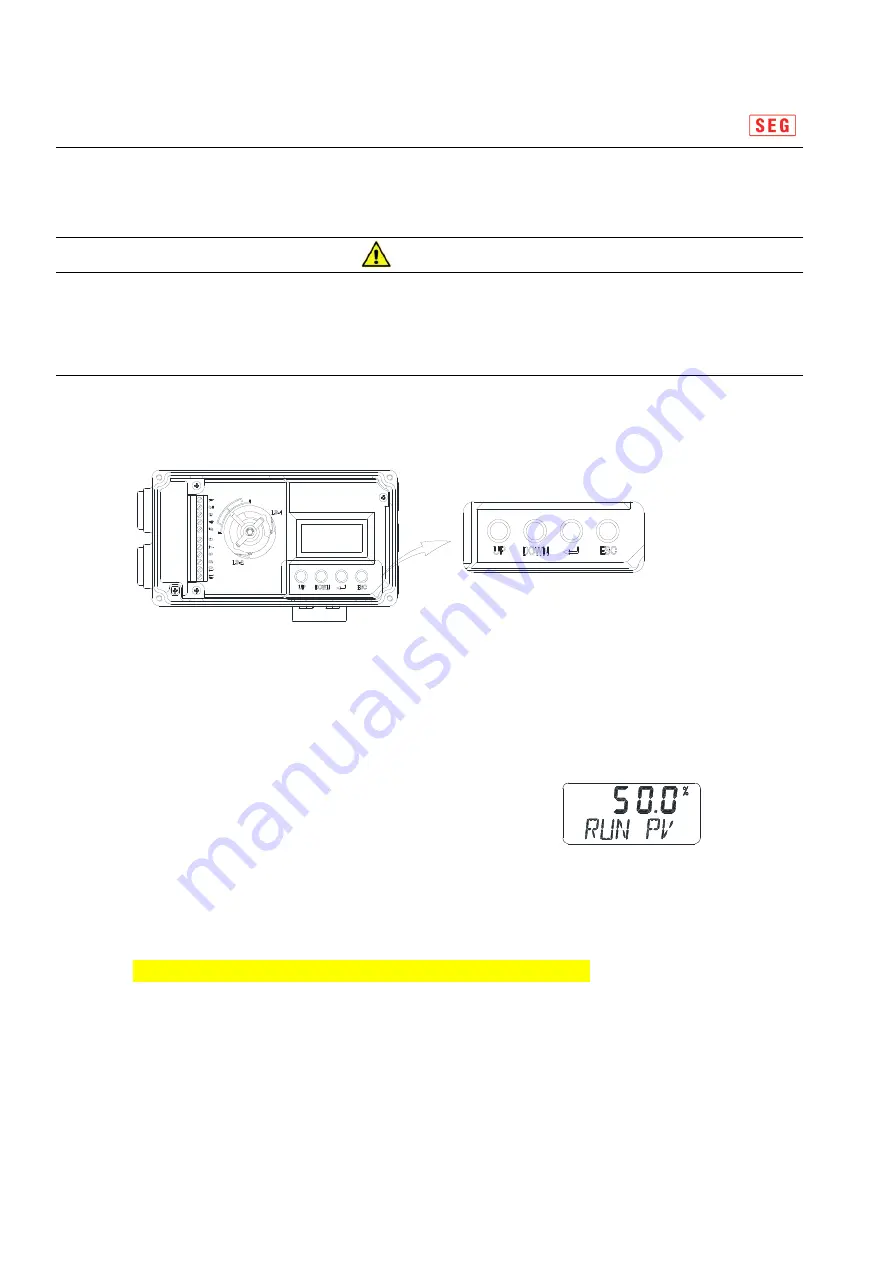
8.2 Button Description
The positioner has four(4) buttons.
Fig 8-1 Button
<UP> & <DOWN> : It is used when m
oving to another menu or changing a parameter value in a menu
<ENTER> : It is used when e
ntering into main menu or sub menu, or designated parameter value
Warning
Before working auto calibration , make sure that they have not influence on overal process
28/40
<ENTER> : It is used when e
ntering into main menu or sub menu, or designated parameter value
<ESC> : It is used when returning
from the current menu to a higher one step menu
8.3 Run Mode( RUN )
After connecting power to the positioner, RUN PV mode shall be
appeared on positioner's LCD monitor after 10 seconds as
described picture. " RUN PV " stands for the current position
of positioner.
"50.0%" indicates that valve opening is 50%.
In "RUN" mode, theere are 7 kinds of type which can be indicated as follows.
1. RUN PV (%) :
Process Value - valve stroke. %
2. RUN SV (%) :
Set Valve - input signal, 0~100%
3. RUN SV (mA) :
Set Valve - input signal, 4~20mA DC
4. RUN VEL :
Velocity - current valve stem's velocity.
5. RUN ERR :
Error - difference between SV and PV
6. RUN PV :
Current Position's resistance value
7. RUN MV :
Torque Motor's digital control value
28/40
Содержание SP740 Series
Страница 14: ...Smart Positioner SP740 Series 2 10 2 SP740 Lever Type 14 40 Fig 2 6 SP740 Lever Type 14 40...
Страница 15: ...Smart Positioner SP740 Series 2 10 3 SP740 Fork Lever Type 15 40 Fig 2 7 SP740 Fork Lever Type 15 40...
Страница 16: ...Smart Positioner SP740 Series 2 10 4 SP740 Namur Type 16 40 Fig 2 8 SP740 Namur Type 16 40...
Страница 39: ...Smart valve positioner SP740 Series 10 LCD Operation Map 39 40 39 40...


