background image

SERVICE MANUAL


iHunter Series


- 14 -


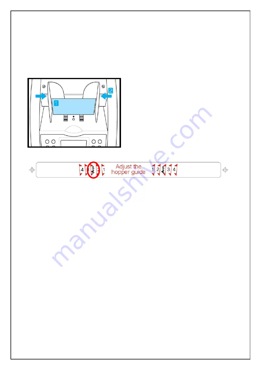
3-3. How to place notes properly on Hopper 


Before count the notes, user is recommended to adjust the hopper guide. 
If you not adjust the hopper guide, the machine does not work properly. 


1. Place a note on the HOPPER referring 

to following figure. 

 
2. Move the HOPPER guide to make the 

guide size is the same with the note 
size. 

 
3. If you use to USD or EURO, refer to   
   symbol of Hopper sticker. 
     

Содержание iHunter 2.0 CIS/FIT

Страница 1: ...SERVICE MANUAL iHUNTER Series REV 1 0 ...

Страница 2: ...ny discrepancies between this manual and the basic agreement or specifications sheet exchanged between seetech and a customer the basic agreement or specifications sheet is to be regarded as correct The contents of this manual apply only to the specified product In principle seetech cannot be held responsible for the application of the manual s contents to other products nor for a third part s com...

Страница 3: ...THE CONSTRUCTION OF SENSORS 12 3 2 DESCRIPTION OF DISPLAY 13 3 3 HOW TO PLACE NOTES PROPERLY ON HOPPER 14 3 4 DECRIPTION OF KEY 15 CHAPTER 4 RS 232C PROTOCOL 4 1 Abstract 16 4 2 System block diagram 16 4 3 SERIAL INTERFACE SPECIFICATION 16 4 4 Flow chart of software 18 4 5 EXAMPLE SOFTWARE USING RS 232C PROTOCOL 19 4 6 Descriptions of Key Pad 21 4 7 Descriptions of COMMAND 21 CHAPTER 5 OPERATION 5...

Страница 4: ...BOARD DISASSEMBLY 55 7 6 CF BOARD DISASSEMBLY 57 7 7 CF REAR MR SENSOR DISASSEMBLY 59 7 8 IR REAR SENSOR DISASSEMBLY option 62 7 9 CIS Contact Image Sensor DISASSEMBLY 65 7 10 UPGRADE EXTERNAL BOARD DISASSEMBLY 66 7 11 DISPLAY BOARD DISASSEMBLY 67 7 12 SMPS DISASSEMBLY 69 7 13 MAIN MOTOR DISASSEMBLY 70 7 14 SUB MOTOR DISASSEMBLY 72 7 15 SOLENOID DISASSEMBLY 74 7 16 KICKER ROLLER RUBBER DISASSEMBLY...

Страница 5: ...OARD SETTING 99 8 2 2 CF BOARD SETTING 106 8 2 3 IR BOARD SETTING 116 8 2 4 CIS BOARD SETTING 122 8 3 DESCRIPTION OF TECHNICAL MENU 129 8 3 1 TECHNICAL SERVICE MENU 129 8 3 2 SUPERVISOR MENU 134 8 3 3 CIS TEST MODE 137 8 3 4 CF LEVEL ADJUST MODE 142 APPENDIX 1 ERROR CODE 148 2 ADJUST THE GAP KNOB 152 3 How to adjust the gap 153 ...

Страница 6: ...rs Excellent Counterfeit Detection i Hunter carries high levels of counterfeit detection with UV FL IR and Superior Magnetic Detection system Most suspect notes will not escape this advanced detection technology Non stop throughout Machine s feed mechanism ensures non stop throughout for variety of functions identifies mixed denomination bills quickly and provides total value and piece count count...

Страница 7: ... iHunter Series 7 1 2 APPEARANCE HOPPER GUIDE Both sides HOPPER LCD DISPLAY WINDOW REJECT POCKET RELEASE BUTTON Both sides STACKER POCKET GAP ADJUSTMENT KNOB REAR COVER CLOSER SERIAL PORT POWER SWITCH POWER CONNECTOR ...

Страница 8: ...SERVICE MANUAL iHunter Series 8 1 3 PACKING LIST BASIC OPTIONS Machine User Manual Power Cable RS232C cable Serial Print cable External Display ...

Страница 9: ...ckets 1pocket and 1reject Feed System Roller friction system Main Pocket Capacity 200notes circulated notes Power supply 100 240V AC 50 60Hz Reject Pocket Capacity Max 90notes circulated notes Power consumption Max 110 Watts OPTIONS Local Currency Max 2 currency IR Detection Full Line IR Sensor External Display LCD type for customer Bill Printout With RS232C Interface for PC and external printer P...

Страница 10: ...will run its best when stored and operated in an environment that meets the following temperature and humidity conditions Operating temperature 5 to 40 Storage temperature 15 to 60 Shipping temperature 40 to 70 Relative Humidity Operating 30 to 70 RH non condensing Storage 20 to 85 RH non condensing Shipping 5 to 90 RH non condensing ...

Страница 11: ... voltage 24 V 5V 7VDC Rated output current 3 0 A 24V 7VDC 0 3 3 0 A 5VDC Rated output power 60W Dimensions and weight Dimensions 187X120X43 mm DC MOTOR HMP 4468 097A Performance Data Input voltage DC 24V No Load Speed 4300R P M Current 0 2A At Maximum Efficiency Speed 3610R P M Current 1 05A Output 15 4W Life 2000H Weight 360g SWING SELECTOR KHA38H01A Specification Swing angle 20 Change position 1...

Страница 12: ... 3 HARDWARE CONFIGURATION 3 1 THE CONSTRUCTION OF SENSORS CIS COUTER SENSOR RX MAIN COUTER SENSOR RX UV SENSOR CIS SENSOR MAIN COUTER SENSOR TX MAGNETIC SENSOR UV SENSOR REJECT POCKET SENSOR REJECT COUNTER SENSOR HOPPER SENSOR STACKER SENSOR ...

Страница 13: ...t Currency Mark Display the current currency Total value of accepted notes Total value of the Stacker Pocket Selected Batch Number Display the current batch number Speed Display the current speed ADD mode activation Whether or not use of ADD function Mix RJP CF 0 0 0 B100 S1000 ADD Use of Reject Counterfeit Detection Operation Mode Number of notes in Stacker Pocket Total value of accepted notes Nu...

Страница 14: ...recommended to adjust the hopper guide If you not adjust the hopper guide the machine does not work properly 1 Place a note on the HOPPER referring to following figure 2 Move the HOPPER guide to make the guide size is the same with the note size 3 If you use to USD or EURO refer to symbol of Hopper sticker ...

Страница 15: ...this key you can adjust the DDL value SPEED Change the count speed for count mode After pressing this key you can adjust the speed by pressing 10 of 1 key ADD When pressing and holding down the key you can enter the cumulate mode CF Counterfeit detection active or deactivate function CURRENCY Choice of currency To enter CIS TEST MODE When pressing and holding down the key PRINT After counting when...

Страница 16: ...ntroller with RS 232 port 4 2 System Block Diagram 4 3 Serial Interface Specification 1 Description of Serial Port for RS 232 PORT Emulation MODE SEETECH RS 232 Protocol This protocol only supply by from SEETECH Baud Rate 2 400 bps 115 200 bps 115 200 bps is a Default Value of Factory Data Bits 8 bits Stop Bits 1 bit Handshaking DTR DSR Parity Check Disable ...

Страница 17: ...Female Pin No Signal Name Signal Direction Contents 1 GROUND Signal Ground 2 7 None 8 RXD Input Receive Data 9 11 None 12 TXD Output Transmit Data 13 15 None 4 Interface signal D SUB 9 PIN Female Pin No Signal Name Signal Direction Contents 1 None 2 RXD Input Receive Data 3 TXD Output Transmit Data 4 None 5 GROUND Signal Ground 6 9 None ...

Страница 18: ... SEND A COMMAND TO MACHINE REPORT READY TO USE RS 232 PORT Is System OK READY RS 232 PORT Does a Command Select SEND COMMAND NO YES YES NO START INITIAL SYSTEM CHECK SYSTEM CHECK MEMORY CHECK SUB PART SEND A REACTION DATA TO COMPUTER OR CONTROLLER READY TO USE RS 232 PORT Operation as a counter Is System OK Does Command receive Command Analysis Perform Command ...

Страница 19: ...e using RS 232C protocol Show to execute the Cyber Operator 1 Connect Machine to PC 2 Execute the cyberOperator exe file 3 Choose the communication ports and baud rate Baud rate is the same as Machine s baud rate And don t change the blue box parameters ...

Страница 20: ... MANUAL iHunter Series 20 4 Click the connect icon then red light changes to green 5 Display shows as below This is the same key pad as Machine If you click the CF icon CF function is activated to the machine ...

Страница 21: ... click the ADD key with the machine will react and display on the screen Press the Key Press and Hold down the Key 4 7 Descriptions of COMMAND If you want to change the batch value it is possible at this COMMAND First select COMMAND TYPE is BATCH Second type COMMAND VALUE you wanted Third click Execute icon If you want to quit this function click Exit ...

Страница 22: ...here is anything wrong the message Check above Press the RESTART will be blinking on the display Checking EEPROM Data OK Checking Setting Data HSRB Sensors OK Checking Count Sensors Cis Up OK Main OK Reject OK Motor Speed Data Main Motor OK Sub Motor OK The machine will show this message below on the DISPLAY for a short time during checking the Sub Modules If there is anything wrong the message Ch...

Страница 23: ...B 1 0 0 S 1 0 0 0 COUNT mode is for counting all other currencies without detection When you place the notes on the Hopper the machine starts running Counted notes are stacked in the Stacker Pocket and the trouble notes are stacked in the Reject Pocket C O U N T R J P 0 0 D D L 5 0 B 1 0 0 S 1 0 0 0 DDL means Double Detection Level User can select the level and the range is 1 to 9 DDL 1 Euro USD D...

Страница 24: ... change the DDL press the LEVEL key and select level Double Detection Level 4 Do you want to save DDL SAVE LEVEL EXIT RESTART When you save the DDL value press and hold down the LEVEL key If you press the LEVEL key DDL value save and go to the COUNT mode ...

Страница 25: ... time If you want to show the error message when the error ocurrs during counting Press and hold down the MODE key Please refer to APPENDIX when the error ocurrs during counting CURRENCY Press CURRENCY key and select Euro MODE Press MODE key and select operation mode you want M i x R J P 0 0 0 B 1 0 0 S 1 0 0 0 It is possible that the machine denominates Euro When you place the notes on the Hopper...

Страница 26: ... time If you want to show the error message when the error ocurrs during counting Press and hold down the MODE key Please refer to APPENDIX when the error ocurrs during counting CURRENCY Press CURRENCY key and select USD MODE Press MODE key and select operation mode you want M i x R J P 0 0 0 B 1 0 0 S 1 0 0 0 When you place the notes on the Hopper the machine starts running Counted notes are stac...

Страница 27: ...to show the error message when the error ocurrs during counting Press and hold down the MODE key Please refer to APPENDIX when the error ocurrs during counting CURRENCY Press CURRENCY key and select currency you want MODE Press MODE key and select operation mode you want When you place the notes on the Hopper the machine starts running Counted notes are stacked in the Stacker Pocket and the troubl...

Страница 28: ...elect Batch Number 10 key or 1 key 10 key is increase ten unit and 1 key is increase one unit If you press and hold BATCH key Batch function is inactive and Batch Number becomes zero But the value of Batch is not saving The default value is 100 If you want Batch Adjusting refer to 7 PRE BATCH PCS SETTING of USER SETTING MODE CF function is performed with other mode except Counting Mode and Serial ...

Страница 29: ...es the sum of counted notes M i x R J P C F 0 0 0 B 1 0 0 S 1 0 0 0 A D D Add M i x R J P C F 0 4 3 5 2 3 B 1 0 0 S 1 0 0 0 A D D current When you place the notes on the Hopper the machine starts running When count the notes the Display shows current information When notes are removed from the Stacker Pocket M i x R J P C F 0 4 3 5 2 3 B 1 0 0 S 1 0 0 0 A D D Add Display shows added information be...

Страница 30: ...n current and previous counted notes If you want to see a report on Display press and hold down PRINT key Display shows added value information ADD VALUE EURO E5 XXX XXX E10 XXX XXX E20 XXX XXX Total Notes E50 XXX XXX X XXX XXX E100 XXX XXX E200 XXX XXX Total Value E500 XXX XXX XX XXX XXX EXIT RESTART KEY If you want to print out a receipt press PRINT key Display shows the message as below during ...

Страница 31: ...0 B 1 0 0 A D D Add Verify function During counting in ADD mode use can verify counting result which already counted after activating ADD function or new bundle of note which is independent with ADD counting result For example after activate ADD function use counts 1200 notes But he wants to count again some notes which were already counted or count new bundle In this case if press ADD Key shortly...

Страница 32: ...d new very new version notes USD only SG MODE Before counting the user can select a specific denomination to be counted SORTING FUNCTIONS Dir MF MODE Separation mode by Facing function all denominations The machine separates front side or rear side of the notes Dir MO MODE Mixed separation mode by Orientation function all denominations The machine separates different direction notes Dir SF MODE Se...

Страница 33: ...0 0 0 After count and remove the note from Stacker Pocket Dispenser function is off automatically Even if remove the note from Stacker Pocket the function is activated continuously If press 1 key again Dispenser function is off manually Or when select another mode by pressing MODE key exit Dispenser Mode Using the key command set the value which you want After set the value exit the MENU using RES...

Страница 34: ... MODE Press MODE key and select SP mode Only the selected denomination will be processed into the Stacker Pocket S G 1 0 0 R J P C F 0 0 0 B 1 0 0 S 1 0 0 0 10 1 Press 10 key or 1 key and select the denomination CURRENCY Press CURRENCY key and select currency you want MODE Press MODE key and select SP mode If user selects this mode the machine send notes to Stacker which have same denomination and...

Страница 35: ...ey or 1 key and select Dir SF mode CURRENCY Press CURRENCY key and select currency you want MODE Press MODE key and select Dir MF mode The machine saves the direction information of the first inserted note D i r M O R J P C F 0 0 0 B 1 0 0 S 1 0 0 0 All other notes with same orientation will be processed into Stacker Pocket 10 1 Press 10 key or 1 key and select Dir MO mode CURRENCY Press CURRENCY ...

Страница 36: ...elect currency you want MODE Press MODE key and select Dir MF mode The machine saves the direction information of the first inserted note D i r S O R J P C F 0 0 0 B 1 0 0 S 1 0 0 0 Notes by same denomination and orientation will be processed into Stacker Pocket 10 1 Press 10 key or 1 key and select Dir SO mode ...

Страница 37: ... 0 0 0 You can count all denomination of selected currency without any selection Before counting in serial number print mode please arrange the notes that the serial number printed side is faced upward For example USD is front side and Euro is rear side After counting the LCD Display will display the message as below Please Wait Printing serial number If you wants to count other notes continually ...

Страница 38: ... SENSOR STACKER SENSOR REGULAR CLEANING OF THE MACHINE The machine has a many sensitive sensor to perform high technology functions for example counterfeit detection denominations recognition of serial number and etc Users are recommended to clean the machine sensors at least once a week Refer to following section and clean the machine regularly Please turn the power off before cleaning the machin...

Страница 39: ...SERVICE MANUAL iHunter Series 39 5 6 TROUBLE SHOOTING Please ask to factory or agent company ...

Страница 40: ...lt Value of Factory Baud Rate 2 400 bps 115 200 bps It is possible that change the setting value of baud rate Please check the setting value before using Data Bits 8 bits Stop Bits 1 bit Handshaking DTR DSR Parity Check Disable Available Serial Printer SAMSUNG SRP 370 SRP 350 etc Web Site HTTP WWW SAMSUNGMINIPRINTERS COM EPSON TM T88III TM T90 etc Web Site HTTP POS EPSON COM ...

Страница 41: ... 1 EXIT PRESS RESTART KEY 2 Find SERIAL PRINTER 3 How to print Manual 4 Print out Type Receipt 5 Blank of tail 5 NEXT HELP CF KEY 1 10 or SERIAL PRINTER MENU 1 2 1 EXIT PRESS RESTART KEY 2 Find SERIAL PRINTER 3 How to print Manual 4 Print out Type Receipt 5 Blank of tail 5 NEXT HELP CF KEY If you changes a setting value the LCD Display will display the message as below during saving the setting va...

Страница 42: ... Blank of tail User set up the blank of tail You can select 4 20 Emulation You can choose Epson or Star type Baud Rate Set up the baud rate between machine and printer You can select 2 400 115 200bps ROLL PAPER Size Set up the size of printer paper You can select 2 or 3 inch Font Size Set up the font size You can select 12x24 or 9x17 HELP CF KEY If you have question about this menu press CF key me...

Страница 43: ...T Press the PRINT key M i x R J P C F 0 9 1 0 1 3 4 5 0 0 B 1 0 0 S 1 0 0 0 Please Wait Printing the data If the notes remain at the Reject Pocket while user press PRINT key following message is displayed If you select the PRINT WARINIG to YES of USER SETTING MODE Please Check Make Rej Pocket empty The machine prints out the receipt It is possible that prints out the receipt normal operation mode ...

Страница 44: ...SERVICE MANUAL iHunter Series 44 THE FORMS OF THE RECEIPT Normal operation mode Active ADD function USD EURO USD EURO ...

Страница 45: ... r r o r 3 N o C I S R e s u l t 0 N o U V M G R e s u l t 0 7 H E L P C F K E Y Count means the number of rejected notes User can move next or previous page pressing 10 key or 1 key When pressing MODE key Display shows the list of type of error MODE Count Error This errors is caused by counting states For example double notes are inserted the note is skewed etc Function Error This error is caused...

Страница 46: ...RINTING YES 4 REJECT POCK ACTIVE YES 5 REJECT POCK SIZE 60 6 NUMBER OF PRINTOUT 1 7 PRE BATCH PCS SETTING NEXT HELP CF KEY If you want to select the value Press PRINT 10 or 1 key PRINT 1 or 10 USER SETTING MODE 1 2 1 EXIT PRESS RESTART KEY 2 ID NONE 3 USER s ID PRINTING YES 4 REJECT POCK ACTIVE YES 5 REJECT POCK SIZE 60 6 NUMBER OF PRINTOUT 1 7 PRE BATCH PCS SETTING NEXT HELP CF KEY If you changes...

Страница 47: ...NEXT HELP CF KEY USER SETTING MODE 2 3 10 PRINT WARNING YES 11 STOP CONDITION DISABLE 12 BAR CODE SEND TO COMPUTER 13 USING CENTER 14 TYPE 2 OF 5 15 LENGTH 18 16 CF KEY NORMAL 17 SERIAL CF MODE 18 BATCH FUNCTION CLEAR TOP HELP CF KEY The page 2 3 of User Setting Mode USER SETTING MODE 3 3 19 Face Orientate NORMAL 20 See the result NORMAL 21 Reject Number SHOW 22 Serial Cutting 200 23 Stacker Warni...

Страница 48: ...or Printer USING Select position of printed bar code TYPE User can select bar code type LENGTH Length means bar code length and user can select this 1 26 CF KEY NORMAL Machine detects all counterfeits EXCEPTION Machine detects counterfeits except special note or denomination SERIAL CF MODE Activate CF function in Serial Mode BATCH FUNCTION CLEAR CLEAR After batch count and remove note from stacker...

Страница 49: ...MODE 1 2 1 EXIT PRESS RESTART KEY 2 ID NONE 3 USER s ID PRINTING YES 4 REJECT POCK ACTIVE YES 5 REJECT POCK SIZE 60 6 NUMBER OF PRINTOUT 1 7 PRE BATCH PCS SETTING 8 SCREEN SAVER 5Min 9 BUZZER VOLUME Middle NEXT HELP CF KEY WRITING USER s ID 0 1 2 3 4 5 6 7 8 9 A B C D E F G H I J K L M N O P Q R S T U V W X Y Z _ a b c d e f g h i j k l m n o p q r s t u v w x y z BackSpace USER s ID 1 Press MODE ...

Страница 50: ... 2 While pressing release button both side lift up the front side of the machine Loosen the screw A A 3 Open the rear cover and loosen the screw B B 4 C Loosen the screw C 5 6 Remove the left side cover and disconnect the harness D Loosen the screw D and Remove the main board from the machine ...

Страница 51: ...g release button both side lift up the front side of the machine Loosen the screw A 3 Open the rear cover and loosen the screw B 4 C Loosen the screw C 5 6 Remove the right side cover and disconnect the harness Loosen the screw D and remove the motor board from the machine A B D ...

Страница 52: ...OVER Loosen the screw B and open the REAR LOWER COVER 3 Open the rear cover and loosen the screw C 4 Loosen the screw D and disconnect the harness E 5 6 Open the HOOK F and pull out the DETECTOR MODULE to arrow The DETECTOR MODULE has a CF CIS board and a many sensors C D E F B REAR LOWER COVER A REAR MIDDLE COVER ...

Страница 53: ... DRAWING The detector module consists of the CF CIS board and many sensors REAR MODULE DISASSEMBLY DETECTOR COVER PLATE CIS BOARD CF BOARD DETECTOR CF COVER CF REAR SENSOR ASSEMBLY MR SENSOR ASSEMBLY DETECTOR MODULE PLATE ASSEMBLY CIS SENSOR IR REAR SENSOR ASSEMBLY ...

Страница 54: ...SERVICE MANUAL iHunter Series 54 FRONT MODULE DISASSEMBLY DETECTOR LOWER PLATE CF FRONT SENSOR ASSEMBLY DETECTOR UV COVER IR FRONT ENSOR ASSEMBLY ...

Страница 55: ...he REAR LOWER COVER Loosen the screw B and open the REAR MIDDLE COVER 3 Open the rear cover and loosen the screw C 4 Loosen the screw D and disconnect the harness E 5 6 Open the HOOK F and pull out the DETECTOR MODULE to arrow Loosen the screw G A C D E F REAR LOWER COVER B REAR MIDDLE COVER G ...

Страница 56: ...AL iHunter Series 56 7 8 Loosen the screw H Loosen the screw I and remove the DETECTOR COVER PLATE 9 Disconnect the harness of CIS board and loosen the Screw J 10 Remove the CIS board from the DETECTOR MODULE H I J ...

Страница 57: ...e REAR LOWER COVER Loosen the screw B and open the REAR MIDDLE COVER 3 Open the rear cover and loosen the screw C 4 Loosen the screw D and disconnect the harness E 5 6 Open the HOOK F and pull out the DETECTOR MODULE to arrow Loosen the screw G A C D E F REAR LOWER COVER B REAR MIDDLE COVER G ...

Страница 58: ...crew I and remove the DETECTOR COVER PLATE 9 Disconnect the harness of CIS board and loosen the Screw J 10 Remove the CIS board from the DETECTOR MODULE and disconnect the harness of CF board H I J 11 12 K Loosen the Screw K Remove the CIS board from the DETECTOR MODULE ...

Страница 59: ...en the REAR LOWER COVER Loosen the screw B and open the REAR MIDDLE COVER 3 Open the rear cover and loosen the screw C 4 Loosen the screw D and disconnect the harness E 5 6 Open the HOOK F and pull out the DETECTOR MODULE to arrow Loosen the screw G A C D E F REAR LOWER COVER B REAR MIDDLE COVER G ...

Страница 60: ...move the DETECTOR COVER PLATE 9 Disconnect the harness of CIS board and loosen the Screw J 10 Remove the CIS board from the DETECTOR MODULE and disconnect the harness of CF board H I J 11 12 K Loosen the Screw K Remove the CIS board from the DETECTOR MODULE and loosen the screw L L ...

Страница 61: ...SERVICE MANUAL iHunter Series 61 13 14 Remove the UPPER SENSOR assembly and loosen the screw M Remove the MR SENSOR assembly ...

Страница 62: ... the REAR LOWER COVER Loosen the screw B and open the REAR MIDDLE COVER 3 Open the rear cover and loosen the screw C 4 Loosen the screw D and disconnect the harness E 5 6 Open the HOOK F and pull out the DETECTOR MODULE to arrow Loosen the screw G A C D E F REAR LOWER COVER B REAR MIDDLE COVER G ...

Страница 63: ...the DETECTOR COVER PLATE 9 Disconnect the harness of CIS board and loosen the Screw J 10 Remove the CIS board from the DETECTOR MODULE and disconnect the harness of CF board H I J 11 12 K Loosen the Screw K Remove the IR REAR SENSOR board from the DETECTOR MODULE and loosen the screw L L ...

Страница 64: ...SERVICE MANUAL iHunter Series 64 13 Remove the IR REAR SENSOR board assembly ...

Страница 65: ... the REAR MIDDLE COVER Loosen the screw B 3 Open the rear cover and loosen the screw C and pull out the detector cover plate to arrow 4 Loosen the screw D both sides 4 points 5 6 Disconnect the harness E and push the hole using the thin tool Step 1 2 CIS will be out to arrow A REAR MIDDLE COVER B C D 1 2 E ...

Страница 66: ...2 While pressing release button both side lift up the front side of the machine Loosen the screw A A 3 Open the rear cover and loosen the screw B B 4 C Loosen the screw C 5 6 Disconnect the harness D and loosen the screw E 4 point Remove the upgrade board from the machine E D ...

Страница 67: ...e lift up the front side of the machine Loosen the screw A and B A 3 Open the rear cover and loosen the screw C C 4 E Loosen the screw D 5 6 Loosen the screw E and remove the left and right side cover from the machine Disconnect the harness F and loosen the screw J and remove the HOPPER GUIDE COVER B D F J ...

Страница 68: ... H 9 Remove the DISPLAY assembly to arrow 10 Disconnect the harness of the DISPLAY board 11 12 Loosen the screw I and remove the DISPLAY board DISPLAY assembly consists of several parts DISPLAY board I DISPLAY board LCD MODULE LCD power board DISPLAY COVER HOPPER SENSOR G H ...

Страница 69: ...SERVICE MANUAL iHunter Series 69 7 12 SMPS DISASSEMBLY 1 2 Loosen the screw A Disconnect the harness B 3 Loosen the screw C 4 points and remove the SMPS A B C SMPS ...

Страница 70: ... lift up the front side of the machine Loosen the screw A and B A 3 Open the rear cover and loosen the screw C C 4 E Loosen the screw D 5 6 Loosen the screw E and remove the left and right side cover from the machine Disconnect the harness F and loosen the screw J and remove the HOPPER GUIDE COVER B D F J ...

Страница 71: ...w K 3 points The MAIN MOTOR will be removed CAUTION Please adjust Kicker and Bite roller timing when assemble the MAIN MOTOR BELT Loosen the screw G Loosen the screw H G H Remove the DISPLAY assembly to arrow Disconnect the harness I and cut the cable tie of the motor harness I 12 MAIN MOTOR BELT K ...

Страница 72: ...lift up the front side of the machine Loosen the screw A and B A 3 Open the rear cover and loosen the screw C C 4 E Loosen the screw D 5 6 Loosen the screw E and remove the left and right side cover from the machine Disconnect the harness F and loosen the screw J and remove the HOPPER GUIDE COVER B D F J ...

Страница 73: ...the MAIN board and loosen the screw L Pull the SUB MOTOR BELT to arrow and loosen the screw M 3 points Loosen the screw G Loosen the screw H G H Remove the DISPLAY assembly to arrow Disconnect the harness I and cut the cable tie of the motor harness I 12 L M SUB MOTOR BELT ...

Страница 74: ...ew A Loosen the screw B 3 Open the front cover and loosen the screw C 4 B Loosen the screw D 5 6 Remove the right side cover and disconnect the harness E Loosen the screw E and remove the solenoid from the machine CAUTION Please adjust position using sorting cam jig when assemble the SOLENOID A C D F E ...

Страница 75: ... side lift up the front side of the machine Loosen the screw A and B A 3 Open the rear cover and loosen the screw C C 4 E Loosen the screw D 5 6 Loosen the screw E and remove the left and right side cover from the machine Disconnect the harness F and loosen the screw J and remove the HOPPER GUIDE COVER B D F J ...

Страница 76: ...NUAL iHunter Series 76 7 8 9 10 11 Pull the RUBBER to arrow Loosen the screw G Loosen the screw H G H Remove the DISPLAY assembly to arrow Turn the KICKER ROLLER and set to the RUBBER on top KICKER ROLLER RUBBER ...

Страница 77: ... side lift up the front side of the machine Loosen the screw A and B A 3 Open the rear cover and loosen the screw C C 4 E Loosen the screw D 5 6 Loosen the screw E and remove the left and right side cover from the machine Disconnect the harness F and loosen the screw J and remove the HOPPER GUIDE COVER B D F J ...

Страница 78: ...g and the belt Pull the BITE UNION ROLLER and BITE ROLLER RUBBER to arrow Loosen the screw G Loosen the screw H G H Remove the DISPLAY assembly to arrow Turn the KICKER or BITE ROLLER and set to the RUBBER on top BITE ROLLER RUBBER 16 E ring BELT BITE UNION ROLLER ...

Страница 79: ... side lift up the front side of the machine Loosen the screw A and B A 3 Open the rear cover and loosen the screw C C 4 E Loosen the screw D 5 6 Loosen the screw E and remove the left and right side cover from the machine Disconnect the harness F and loosen the screw J and remove the HOPPER GUIDE COVER B D F J ...

Страница 80: ...he E ring and washers from the SPLIT ROLLER assembly CAUTION Please adjust insert gap when assemble the SPLIT roller assembly Loosen the screw G Loosen the screw H G H Remove the DISPLAY assembly to arrow Lift up the SPLIT TILT ROLLER to arrow and remove it ...

Страница 81: ...e lift up the front side of the machine Loosen the screw A and B A 3 Open the rear cover and loosen the screw C C 4 E Loosen the screw D 5 6 Loosen the screw E and remove the left and right side cover from the machine Disconnect the harness F and loosen the screw J and remove the HOPPER GUIDE COVER B D F J ...

Страница 82: ...ICE MANUAL iHunter Series 82 7 8 9 10 11 Loosen the screw J and remove the REJECT SENSOR assembly Loosen the screw G Loosen the screw H G H Remove the DISPLAY assembly to arrow Disconnect the harness I J I ...

Страница 83: ...SERVICE MANUAL iHunter Series 83 7 20 REJECT POCKET DISASSEMBLY 1 2 Loosen the screw A Lift up the front side of the REJECT POCKET Hold the point B and remove the REJECT POCKET to arrow 3 A B ...

Страница 84: ...button both side lift up the front side of the machine Loosen the screw A and B A 3 Open the rear cover and loosen the screw C C 4 E Loosen the screw D 5 6 Loosen the screw E and remove the left and right side cover from the machine Loosen the screw F and remove the lower left side cover B D F ...

Страница 85: ...wer right side cover Loosen the screw H and I 9 Lift up the STACKER COVER assembly and disconnect the harness J and cable tie CAUTION The harness is very short 10 Remove the STACKER COVER 11 STACKER COVER assembly consists of two sensors and cover G H I J PHOTO LED PHOTO TR ...

Страница 86: ...ease button both side lift up the front side of the machine Loosen the screw A A 3 Open the rear cover and loosen the screw B B 4 C Loosen the screw C 5 6 Remove the left side cover Open the rear cover and tighten the real time board mount D using the flat head screw E M3X8 2 points E D ...

Страница 87: ...ssemble the Real time board and tighten the screw F and connect the harness G 9 10 Open the rear cover and tighten the screw I 11 Lift up the front cover and tighten the screw J F G H Assemble the left side cover and tighten the screw H I J ...

Страница 88: ...lease button both side lift up the front side of the machine Loosen the screw A Open the rear cover and loosen the screw B 4 B 1 2 3 C Loosen the screw C 5 6 Loosen the screw A and open the REAR MIDDLE COVER Loosen the screw B and open the REAR LOWER COVER E REAR LOWER COVER D REAR MIDDLE COVER A ...

Страница 89: ... 8 F Disconnect the all harness from IR main board and loosen the screw F Remove IR main board from the machine 9 10 Disconnect the all harness from IR connector board and loosen the screw G Remove IR connector board from the machine G ...

Страница 90: ...upgrade machine according to this chapter ex1 software upgrade software bugs function upgrade additional technical part additional hardware etc ex2 additional option Old New serial number function etc 8 1 UPGRADE INSTRUCTION 1 Connect Power cable to the machine 2 Connect serial cable 15P 15P between the machine and upgrade board 3 Connect the cable USB or Serial cable 9P 9P between upgrade board a...

Страница 91: ...LED TEST THIS IS ONLY TECHNICIAN OFF OFF OFF OFF ON OFF OFF OFF RAM TEST OFF OFF OFF OFF OFF ON OFF OFF 57 600 BPS TEST OFF OFF OFF OFF OFF OFF ON OFF 115 200 BPS TEST OFF OFF OFF OFF OFF OFF OFF ON USB TEST Baud rate is related with upgrade speed When use USB the upgrade speed is three times faster than using serial cable 5 Turn on power the machine and upgrade board 6 If use USB after connecting...

Страница 92: ...SERVICE MANUAL iHunter Series 92 Select the driver folder what we sent and click the OK button Click the Next button Select the second box and Click the Browse ...

Страница 93: ...SERVICE MANUAL iHunter Series 93 Click the Continue Anyway button ...

Страница 94: ...SERVICE MANUAL iHunter Series 94 It is possible that actual instruction is little different by PC conditions After install Driver you don t need install again in same PC ...

Страница 95: ... iHunter Series 95 7 Execute the PC_UPGRADE_USB_V0_90 exe Click the connect key When click connect key key is changed by USB Exit If you want to exit USB connection click USB Exit Click File Load to load upgrade file ...

Страница 96: ...ck the SysCheck After self checking the result is shown on the window Select the part which you want to upgrade If you select ALL upgrade all of board Currency code AA ZZ Default value 4 Main software version 80 means 8 0 CIS Master software version CIS Slave software version CF software version IR software version CIS light source UV rank ...

Страница 97: ...SERVICE MANUAL iHunter Series 97 Click the Upgrade Start Upgrade is started Check the FND of the upgrade board If display stays 0 for more than 1 minute try to upgrade again or check the connection ...

Страница 98: ...1 30 This is option TOTAL TIME 12 It is possible that actual upgrade time using USB is little different by PC conditions 8 Exit the PC_UPGRADE_USB_V0_90 exe 9 Turn off the machine and upgrade board 10 Remove the cable of the machine and upgrade board 11 We recommend after completing upgrading calibrate the machine again If the upgrade is successful the following message will be shown ...

Страница 99: ... standard counting Mode 3 Press and hold down the RESTART Key The LCD DISPLAY shows as below 4 Enter the PIN CODE Press and hold down 10 CURRENCY Press and hold down RESTART CF CURRENCY MODE PRINT 5 Display shows as below 6 To exit the TECHNICAL SERVICE MENU press the RESTART key T E C H N I C A L S E R V I C E M E N U P I N C O D E P I N C O D E a p p r o v e d E X I T R E S T A R T K E Y T E C H...

Страница 100: ... and select the item3 3 COUNT SENSORS 13 Press PRINT key and enter the item 3 3 COUNT SENSORS 14 Display shows as below S E L E C T S E T T I N G S E N S O R G R O U P 1 E X I T P R E S S R E S T A R T K E Y 2 H S R B S E N S O R 3 C O U N T S E N S O R S 4 M O T O R S P E E D C A L I B R A T I N G S E L E C T S E T T I N G S E N S O R G R O U P 1 E X I T R E S T A R T K E Y 2 M A I N P A R T 3 C ...

Страница 101: ... 0 9 5 x 2 0 2 0 x X C O U N T S E N S O R S S E T T I N G M O D E E X I T S A V E L O A D S e n O f f s e t s S e t V a l u e S e t S o r s L R L R t i n g C i s 4 0 9 5 4 0 9 5 x 4 0 4 0 x X M a i n 4 0 9 5 4 0 9 5 x 3 0 3 0 x X R e j 4 0 9 5 4 0 9 5 x 2 0 2 0 x X C O U N T S E N S O R S S E T T I N G M O D E E X I T S A V E L O A D S e n O f f s e t s S e t V a l u e S e t S o r s L R L R t i n...

Страница 102: ...tion Cards for Count Sensor 160mm 75mm NEW C O U N T S E N S O R S S E T T I N G M O D E E X I T S A V E L O A D S e n O f f s e t s S e t V a l u e S e t S o r s L R L R t i n g C i s 4 0 9 5 4 0 9 5 x 5 3 3 5 x O M a i n 4 0 9 5 4 0 9 5 x 3 0 3 0 x X R e j 4 0 9 5 4 0 9 5 x 1 6 1 4 x O C O U N T S E N S O R S S E T T I N G M O D E E X I T S A V E L O A D S e n O f f s e t s S e t V a l u e S e t...

Страница 103: ...O M a i n 4 0 9 5 4 0 9 5 o 3 2 4 5 o O R e j 4 0 9 5 4 0 9 5 x 1 6 1 4 x O C O U N T S E N S O R S S E T T I N G M O D E E X I T S A V E L O A D S e n O f f s e t s S e t V a l u e S e t S o r s L R L R t i n g C i s 4 0 9 5 4 0 9 5 x 5 3 3 5 x O M a i n 4 0 9 5 4 0 9 5 o 3 0 3 0 o X R e j 4 0 9 5 4 0 9 5 x 1 6 1 4 x O Put the calibration card on HOPPER Turn the KICKER ROLLER and insert the card ...

Страница 104: ...x x x 4 0 0 x x x x x x x x x x x 5 0 0 x x x x x x x x x x x T E S T M O T O R S P E E D S E T T I N G M O D E T S M C S M M M S M 1 0 0 0 x x x x x x x x 2 0 0 0 x x x x x x x x 3 0 0 0 x x x x x x x x 4 0 0 0 x x x x x x x x 5 0 0 0 x x x x x x x x T E S T C O U N T S E N S O R S S E T T I N G M O D E E X I T S A V E L O A D S e n O f f s e t s S e t V a l u e S e t S o r s L R L R t i n g C i ...

Страница 105: ...x x x 5 0 0 0 x x x x x x x x T E S T M O T O R S P E E D S E T T I N G M O D E E X I T R E S T A R T S A V E v p w m P R I N T S A V E v o n l y C F T E S T x x x x x x x x M O T O R S P E E D S E T T I N G M O D E T S M C S M M M S M 1 1 0 0 x x x x x x x x x x x x 1 2 0 0 x x x x x x x x x x x x 1 3 0 0 x x x x x x x x x x x x 1 4 0 0 x x x x x x x x x x x x 1 5 0 0 x x x x x x x x x x x x T E ...

Страница 106: ...on the LCD DISPLAY Any Currency Mode is available to calibrate the machine 3 Press and hold down the RESTART Key The machine show below message on the LCD DISPLAY 4 Enter the PIN CODE Press and hold down 10 CURRENCY Press and hold down RESTART CF CURRENCY MODE PRINT 5 Display shows as below T E C H N I C A L S E R V I C E M E N U P I N C O D E P I N C O D E a p p r o v e d E X I T R E S T A R T K ...

Страница 107: ...ress the MODE key and select the item 1 1 EUROPEAN S E L E C T S E T T I N G C U R R E N C Y E X I T 6 K O R E A 7 I S R A E L 8 S A U D I A R A B I A 9 J A P A N 1 0 P E R U 1 1 E N G L A N D 1 2 U A E M I R A T E S CF UV MG CURRENCY IR S E L E C T S E T T I N G C U R R E N C Y E X I T 1 E U R O P E A N 2 A M E R I C A 3 S Y R I A 4 S O U T H A F R I C A 5 T U R K E Y S E L E C T S E T T I N G S ...

Страница 108: ...ct the item 1 1 UV MODE Prepare the Black setting paper as below Put the Black setting paper on Hopper and press the PRINT key 1 _ 1 U V O F F S E T S E T T I N G C E U R B L 3 9 B R 3 9 O F F R E F E X I T C H L P R D E R P R D E U 1 4 3 2 3 6 1 4 6 2 3 6 B 1 3 6 1 4 6 1 3 1 1 5 3 F 1 3 3 1 3 2 1 2 9 1 4 8 C 1 2 6 2 1 7 1 2 8 2 2 2 I n s e r t B l a c k P a p e r C F G R O U P O F E U R O P E A N...

Страница 109: ...same the paper of CF series Please use it separates certainly 1 _ 1 U V O F F S E T S E T T I N G C E U R B L 3 9 B R 3 9 O F F R E F E X I T C H L P R D E R P R D E U 1 4 3 2 3 6 1 4 6 2 3 6 B 1 3 6 1 4 6 1 3 1 1 5 3 F 1 3 3 1 3 2 1 2 9 1 4 8 C 1 2 6 2 1 9 1 2 6 1 8 2 C a l i b r a t i o n o f f s e t 1 _ 2 U V G A I N S E T T I N G C E U R B L 3 9 B R 3 9 G A I N R E F E X I T C H L E F T R I G ...

Страница 110: ... T U V S E T T I N G C O M P L E T E 1 _ 2 U V G A I N D E T A I L M O D E C E U R I n s e r t 1 0 P a p e r T U N E R M a x M E A S U R E R M i n U S L 3 6 X X X 3 4 R 3 6 X X X 3 4 B S L 3 6 X X X 3 4 R 3 6 X X X 3 4 F S L 2 6 X X X 2 4 R 2 6 X X X 2 4 R E P E A T D E T A I L T U N E 1 _ 2 U V G A I N D E T A I L M O D E C E U R I n s e r t 1 0 P a p e r T U N E R M a x M E A S U R E R M i n U S...

Страница 111: ... D A T A L O A D 4 F A C T O R Y S E T T I N G L O A D 5 S E R I A L T R A N S S E L E C T S E T T I N G C U R R E N C Y E X I T 1 E U R O P E A N 2 A M E R I C A 3 S Y R I A 4 S O U T H A F R I C A 5 T U R K E Y C F G R O U P O F E U R O P E A N E X I T 1 U V M O D E 2 M G M O D E 3 D E F A U L T D A T A L O A D 4 F A C T O R Y S E T T I N G L O A D 5 S E R I A L T R A N S 1 _ 2 U V G A I N S E T...

Страница 112: ...e RESTART key and exit UV GAIN SETTING mode 39 Press the RESTART key and exit mode If all currencies finished calibration press the RESTART key and exit mode Mix RJP CF 0 0 0 B100 S1000 C F G R O U P O F L O C A L C U R R E N C Y E X I T 1 U V M O D E 2 M G M O D E 3 D E F A U L T D A T A L O A D 4 F A C T O R Y S E T T I N G L O A D 5 S E R I A L T R A N S S E L E C T S E T T I N G C U R R E N C ...

Страница 113: ...sage on the LCD DISPLAY 4 Enter the PIN CODE Press and hold down 10 CURRENCY Press and hold down RESTART CF CURRENCY MODE PRINT 5 Display shows as below 6 If you want to exit the TECHNICAL SERVICE MENU press the RESTART key T E C H N I C A L S E R V I C E M E N U P I N C O D E P I N C O D E a p p r o v e d E X I T R E S T A R T K E Y T E C H N I C A L S E R V I C E M E N U P I N C O D E E X I T R ...

Страница 114: ...F PART Press the CF key and display shows as below 15 Press the MODE key and select the item 1 1 EUROPEAN CF UV MG CURRENCY IR S E L E C T S E T T I N G C U R R E N C Y E X I T 1 E U R O P E A N 2 A M E R I C A 3 S O U T H A F R I C A 4 S Y R I A S E L E C T S E T T I N G S E N S O R G R O U P 1 E X I T R E S T A R T K E Y 2 M A I N P A R T 3 C F P A R T 4 C I S P A R T 5 Q C R E P O R T S E L E C...

Страница 115: ...L O A D 5 S E R I A L T R A N S 2 M G T E S T M O D E C E U R D 5 V e r s O L D T E S T T H R E A D E X I T C H I C H 2 C H 3 C H 4 C H 5 C H 6 M I N 2 3 2 8 4 0 3 6 2 8 2 1 M A X 2 3 2 8 4 0 3 6 2 8 2 1 T H R E A D 2 0 T O T A L 1 7 6 1 7 6 U V T E S T 2 M G T E S T M O D E C E U R D 5 V e r s O L D T E S T T H R E A D E X I T C H I C H 2 C H 3 C H 4 C H 5 C H 6 M I N X X X X X X X X X X X X X X ...

Страница 116: ...message on the LCD DISPLAY 4 Enter the PIN CODE Press and hold down 10 CURRENCY Press and hold down RESTART CF CURRENCY MODE PRINT 5 Display shows as below 6 If you want to exit the TECHNICAL SERVICE MENU press the RESTART key T E C H N I C A L S E R V I C E M E N U P I N C O D E P I N C O D E a p p r o v e d E X I T R E S T A R T K E Y T E C H N I C A L S E R V I C E M E N U P I N C O D E E X I T...

Страница 117: ...play shows as below 17 Press the MODE key and select the item 1 IR OFFSET SETTING 18 Press the PRINT key and enter the item 1 IR OFFSET SETTING CF UV MG CURRENCY IR I R S E T T I N G S E L E C T E X I T 1 I R O F F S E T S E T T I N G 2 I R G A I N S E T T I N G 3 I R V I E W I M A G E S E L E C T S E T T I N G S E N S O R G R O U P 1 E X I T R E S T A R T K E Y 2 M A I N P A R T 3 C F P A R T 4 C...

Страница 118: ... F S E T S E T T I N G D I R F O F F E X I T C H 1 2 5 5 2 5 5 C H 9 2 5 5 2 5 5 C H 2 2 5 5 2 5 5 C H 1 0 2 5 5 2 5 5 C H 3 2 5 5 2 5 5 C H 1 1 2 5 5 2 5 5 C H 4 2 5 5 2 5 5 C H 1 2 2 5 5 2 5 5 C H 5 2 5 5 2 5 5 C H 1 3 2 5 5 2 5 5 C H 6 2 5 5 2 5 5 C H 1 4 2 5 5 2 5 5 C H 7 2 5 5 2 5 5 C H 1 5 2 5 5 2 5 5 C H 8 2 5 5 2 5 5 C H 1 6 2 5 5 2 5 5 175mm 140mm It is differ from CF setting paper Insert...

Страница 119: ... 1 8 O C H 2 6 O C H 3 O C H 1 1 X C H 1 9 O C H 2 7 O C H 4 O C H 1 2 X C H 2 0 O C H 2 8 O C H 5 O C H 1 3 O C H 2 1 O C H 2 9 O C H 6 O C H 1 4 O C H 2 2 O C H 3 0 O C H 7 O C H 1 5 O C H 2 3 O C H 3 1 O C H 8 O C H 1 6 O C H 2 4 O C H 3 2 O 1 _ 1 I R O F F S E T S E T T I N G D I R F O F F E X I T C H 1 O C H 9 O C H 1 7 O C H 2 5 O C H 2 O C H 1 0 O C H 1 8 O C H 2 6 O C H 3 O C H 1 1 O C H 1...

Страница 120: ...A I N S E T T I N G D I R F T Y P E R L P A P E R 1 0 G A I N D E T A I L E X I T C H 1 O C H 9 O C H 1 7 O C H 2 5 O C H 2 O C H 1 0 O C H 1 8 O C H 2 6 O C H 3 O C H 1 1 O C H 1 9 O C H 2 7 O C H 4 O C H 1 2 O C H 2 0 O C H 2 8 O C H 5 O C H 1 3 O C H 2 1 O C H 2 9 O C H 6 O C H 1 4 O C H 2 2 O C H 3 0 C H 7 C H 1 5 C H 2 3 C H 3 1 C H 8 C H 1 6 C H 2 4 C H 3 2 175mm 140mm Insertion direction 17...

Страница 121: ...fferent from displayed number following message shows 1 _ 2 I R G A I N S E T T I N G D I R F T Y P E R L P A P E R 1 0 G A I N D E T A I L E X I T C h e c k P a p e r N u m b e r C H 8 0 C H 1 6 0 C H 2 4 0 C H 3 2 0 1 _ 2 I R G A I N S E T T I N G D I R F T Y P E R L P A P E R 1 0 G A I N D E T A I L E X I T R e t r y S e t t i n g P a p e r C H 8 0 C H 1 6 0 C H 2 4 0 C H 3 2 0 1 _ 2 I R G A I ...

Страница 122: ... the opposite side of CIS sensor 1 Turn the power on 2 The machine show below message on the LCD DISPLAY Any Operation Mode is available to calibrate the machine except standard counting Mode CIS sensor surface glass Opposite side of CIS sensor Clean here by soft cloths Clean here by soft cloths Mix RJP CF 0 0 0 B100 S1000 ...

Страница 123: ...and enter SELECT SETTING SENSOR GROUP The item No 4 is selected 8 Press the MODE key and select the item 4 CIS PART 9 Press the PRINT key and enter the item 4 CIS PART 10 Display shows as below S E L E C T S E T T I N G S E N S O R G R O U P 1 E X I T R E S T A R T K E Y 2 M A I N P A R T 3 C F P A R T 4 C I S P A R T 5 Q C R E P O R T T E C H N I C A L S E R V I C E M E N U P I N C O D E P I N C ...

Страница 124: ...olth 14 Put the jig to CIS sensor as following procedure Calibration paper 1 W h i t e P a p e r S e t t i n g 2 B l a c k P a p e r S e t t i n g 3 L i g h t V a l u e 0 5 2 4 U S D N V M o d e N O 5 E X I T W A v g 1 9 2 2 2 1 1 6 8 1 9 2 W M i n 1 6 8 1 8 5 1 2 3 1 5 3 B A v g 0 0 4 0 0 8 0 0 0 0 0 8 B M a x 0 0 8 0 1 5 0 0 3 0 1 2 ...

Страница 125: ...SERVICE MANUAL iHunter Series 125 Open Rear Cover Prepare CIS jig After set the calibration paper opposite CIS sensor part and put the jig on the left side of CIS sensor referring to picture 1 2 3 ...

Страница 126: ...ector module The metal plate holds the detector module 4 5 6 7 8 Cautions Before put the jig check the calibration paper side which is scratched or not If the paper parts is damaged the calibration does not proper In this case please replace the paper with new one We support the Gray paper type with calibration cards which is tape type ...

Страница 127: ... 5 1 2 3 1 5 3 B A v g 0 0 4 0 0 8 0 0 0 0 0 8 B M a x 0 0 8 0 1 5 0 0 3 0 1 2 1 W h i t e P a p e r S e t t i n g 2 B l a c k P a p e r S e t t i n g 3 L i g h t V a l u e 0 5 2 4 U S D N V M o d e N O 5 E X I T W A v g 1 9 2 2 2 1 1 6 8 1 9 2 W M i n 1 6 8 1 8 5 1 2 3 1 5 3 B A v g 0 0 4 0 0 8 0 0 0 0 0 8 B M a x 0 0 8 0 1 5 0 0 3 0 1 2 1 W h i t e P a p e r S e t t i n g 2 B l a c k P a p e r S...

Страница 128: ...eparate about new and very new US dollar It is more better reduce to rejection rate 22 Select NO or YES using the PRINT key if you want 23 Press the RESTART key to save data and exit CIS SETTING MODE 1 W h i t e P a p e r S e t t i n g 2 B l a c k P a p e r S e t t i n g 3 L i g h t V a l u e 0 5 2 4 U S D N V M o d e N O 5 E X I T W A v g 1 9 2 2 2 1 1 6 8 1 9 2 W M i n 1 6 8 1 8 5 1 2 3 1 5 3 B ...

Страница 129: ...AY 4 Enter the PIN CODE Press and hold down 10 CURRENCY Press and hold down RESTART CF CURRENCY MODE PRINT 5 Display shows as below 6 If you want to exit the TECHNICAL SERVICE MENU press the RESTART key 7 Press and hold down the 1 key until the machine show below message on the LCD DISPLAY T E C H N I C A L S E R V I C E M E N U P I N C O D E P I N C O D E a p p r o v e d E X I T R E S T A R T K E...

Страница 130: ... Y T E C H N I C A L S E R V I C E M E N U 2 3 8 E N C O D E R T E S T A D J U S T I N G 9 L C D B A C K L I G H T T E S T 1 0 S E P A R A T O R T E S T 1 1 S K E W T E S T 1 2 S E L F T E S T R E P O R T 1 3 H S R B S E N S O R S A D J U S T I N G 1 4 C O U N T S E N S O R S A D J U S I N G N E X T H E L P C F K E Y M A C H I N E I N F O R M A T I O N P r o d u c t i o n D a t e 2 0 0 5 0 6 1 3 S...

Страница 131: ...0 8 7 0 8 5 0 2 0 0 0 1 7 0 4 1 6 8 4 3 0 0 0 2 1 9 4 2 1 7 4 4 0 0 0 2 7 9 0 2 7 7 0 5 0 0 0 3 2 1 0 3 1 9 0 T E S T 0 P R E B A T C H P C S A D J U S T I N G E X I T D E F A U L T S A V E T h e U n i t o f c a l c 1 0 B A T C H 1 1 0 0 B A T C H 2 5 0 B A T C H 3 2 5 B A T C H 4 2 0 B A T C H 5 1 0 B A T C H 6 0 S O F T W A R E I N F O R M A T I O N 1 S M A 0 5 7 R R X E U 0 0 6 0 2 9 0 0 0 2 S ...

Страница 132: ...ADJUSTING Press the PRINT key and check sensor 14 COUNT SENSOR ADJUSTING Press the PRINT key and starts sensor setting If you stop the setting press the PRINT key 15 RELOAD FACTORY SETTING Reload the machine setting to factory setting Be cardful initialized all of setting 16 LANGUAGE Display the current language 17 COUNTING Select counting mode AUTO or External AUTO When user place the notes on th...

Страница 133: ...IME It is same of 19 SETTING DATA S E T T I N G D A T E T I M E Y Y Y Y M D D W D 2 0 0 5 1 1 0 5 F R I H H M M S S 1 1 4 9 3 9 E X I T R E S T A R T K E Y Do you change value YES CURRENT NO RESTART 1 Select the position what you want to change using the MODE key view the line 2 Change the value using 10 or 1 key 3 If finishing set date press PRINT key 4 Display shows as below If you want to save ...

Страница 134: ...essage on the LCD DISPLAY 4 Enter the PIN CODE Press and hold down 10 CURRENCY Press and hold down RESTART CF CURRENCY MODE PRINT 5 Display shows as below 6 If you want to exit the TECHNICAL SERVICE MENU press the RESTART key T E C H N I C A L S E R V I C E M E N U P I N C O D E P I N C O D E a p p r o v e d E X I T R E S T A R T K E Y T E C H N I C A L S E R V I C E M E N U P I N C O D E E X I T ...

Страница 135: ...on activate always 3 CF WARNING Select the CF warning display If you select ENABLE and rejected notes cause of CF error Display shows as below Blinking the message twice and Display shows as below CF Error is detected S U P E R V I S O R M E N U 1 1 1 E X I T P R E S S R E S T A R T K E Y 2 C F F U C N T I O N C F K E Y 3 C F W A R N I N G D I S A B L E 4 P R I N T E R C U T T E R E N A B L E 5 E ...

Страница 136: ...int the error code report to printer in operation mode SERIAL Print the error code report to printer in serial mode BOTH Print the error code report to printer in operation and serial mode 6 PROTOCOL TYPE Select protocol type iHUNTER Other 7 PROTOCOL SEND Select the control type By command Control by command After counting After counting automatically send the protocol Mix RJP CF 2 27 423 B100 S10...

Страница 137: ...T Key The LCD DISPLAY shows as below 4 Enter the PIN CODE Press and hold down 10 CURRENCY Press and hold down RESTART CF CURRENCY MODE PRINT 5 Display shows as below 6 To exit the TECHNICAL SERVICE MENU press the RESTART key T E C H N I C A L S E R V I C E M E N U P I N C O D E P I N C O D E a p p r o v e d E X I T R E S T A R T K E Y T E C H N I C A L S E R V I C E M E N U P I N C O D E E X I T R...

Страница 138: ...Y E U R O 7 N O R M A L F U L L I M A G E V I E W 8 S E R I A L F U L L I M A G E V I E W T O P H E L P C F K E Y C I S V e r s i o n I n f o r m a t i o n S e r i a l N u m b e r D a t e 2 0 0 6 0 3 2 0 A C W H 3 0 0 1 T 0 1 0 1 0 2 T 0 1 0 2 0 6 N 0 1 0 X X X X X X X X X X X X X X C I S T E S T M O D E O K 1 2 1 E X I T P R E S S R E S T A R T K E Y 2 C I S S O F T W A R E V E R S I O N 3 C I S ...

Страница 139: ...S sensor Red box is 4 channel state of CIS sensor If there is problem ex serious dirty or CIS channel dead or CIS board damage Display show X mark of problem channel 1 W h i t e P a p e r S e t t i n g 2 B l a c k P a p e r S e t t i n g 3 L i g h t V a l u e 0 5 2 4 U S D N V M o d e N O 5 E X I T W A v g 2 5 3 2 4 6 2 5 2 2 2 1 W M i n 2 3 5 2 1 3 1 9 5 2 1 5 B A v g 0 0 9 0 1 1 0 0 8 0 1 5 B A ...

Страница 140: ...ex 01 is Skew left error Refer to Appendiex 2 Error code for more detail 3 PC This mode is for developer 4 BOTH Display show LCD and PC information of notes 5 FILE Save information of notes to PC using software 6 ALL See information of notes to PC using software You can see error information of notes why reject and can select error code using 10 or 1 key CIS Information Page 01 02 001 0 2 154 65 N...

Страница 141: ... you want to see CIS image using PRINT Key before see full image of note 7 NORMAL FULL IMAGE VIEW You can see full image of note using software 8 SERIAL FULL IMAGE VIEW You can see big full image of note using software This image is real size This image is real size ...

Страница 142: ...Operation Mode is available to calibrate the machine except standard counting Mode 3 Press and hold down the RESTART Key The LCD DISPLAY shows as below 4 Enter the PIN CODE Press and hold down 10 CURRENCY Press and hold down RESTART CF CURRENCY MODE PRINT 5 Display shows as below 6 To exit the TECHNICAL SERVICE MENU press the RESTART key T E C H N I C A L S E R V I C E M E N U P I N C O D E P I N ...

Страница 143: ...s below This is ready for adjustment detect the counterfeit note 11 To exit the Mode press RESTART key 12 Put the counterfeit on the Hopper and adjust the Hopper guide The machine start adjustment of UV level 13 Put the counterfeit on the Hopper 3 5 times of each direction 4 directions C F L E V E L A D J U S T U S D E X I T 1 C O U N T E R F E I T 2 G E N U I N E 3 A D J L E V E L S A V E 4 D E F...

Страница 144: ...terfeit test again about each directions If the machine not detect the counterfeit try again process 10 18 If the machine not detect the counterfeit again contact to us Mix RJP CF 0 0 0 B100 S1000 C F L E V E L A D J U S T U S D E X I T 1 C O U N T E R F E I T 2 G E N U I N E 3 A D J L E V E L S A V E 4 D E F A U L T L O A D D i s a b l e C F L E V E L A D J U S T U S D E X I T 1 C O U N T E R F E...

Страница 145: ...EVEL SAVE and press PRINT key for saving the UV level Display show as below 23 To exit CF LEVEL ADJUST Mode press RESTART key 24 If the rejection rate is over 5 press and hold down CF key C F L E V E L A D J U S T U S D E X I T 1 C O U N T E R F E I T 2 G E N U I N E 3 A D J L E V E L S A V E 4 D E F A U L T L O A D A d j u s t S a v e O K C F L E V E L A D J U S T U S D E X I T 1 C O U N T E R F ...

Страница 146: ...hold down CF key To enter the CF LEVEL ADJUST Mode press CF key C F L E V E L A D J U S T U S D E X I T 1 C O U N T E R F E I T 2 G E N U I N E 3 A D J L E V E L S A V E 4 D E F A U L T L O A D G e n u i n e E n a b l e CF UV MG CURRENCY IR C F L E V E L A D J U S T U S D E X I T 1 C O U N T E R F E I T 2 G E N U I N E 3 A D J L E V E L S A V E 4 D E F A U L T L O A D G e n u i n e E n a b l e C F...

Страница 147: ... Mode press RESTART key 31 Test again genuine and counterfeit notes 32 If the machine not detect the counterfeit try again process 10 18 If the machine not detect the counterfeit again contact to us C F L E V E L A D J U S T U S D E X I T 1 C O U N T E R F E I T 2 G E N U I N E 3 A D J L E V E L S A V E 4 D E F A U L T L O A D D i s a b l e ...

Страница 148: ...ejected user can check the rejection report Please do not remove the note from reject pocket press and hold MODE key The display shows as below Count means the number of rejected notes User can move next or previous page pressing 10 key or 1 key And when pressing RESTART key return to operating mode display Value Error E101 means that when the note insert to the machine it skewed to the left Pleas...

Страница 149: ...fed E006 Half Error Bill was fed E007 Dispenser full Dispenser function is completed Remove notes from the Reject Pocket and Stacker Pocket E008 Separator error There is no time to operate separater Remove notes from the Reject Pocket and Stacker Pocket and restart E009 Front cover opened Front cover is opened A note is in the machine 1 Open front cover and remove notes in the machine 2 Restart co...

Страница 150: ...ror E107 Dimension Currency Y length E108 Value Error E108 Dimension Currency X Y length E109 Value Error E109 Uncertain Error E110 Value Error E110 Different Currency E111 Value Error E111 Chain error E112 Value Error E112 Side slope Left Right slope difference E113 Value Error E113 Fanwise Original X Length E114 Value Error E114 Fanwise Original Y Length E115 Value Error E115 Fanwise Original X ...

Страница 151: ...ure for removing the cause of error E221 E C1 A note is skewed Restart counting operation E222 E C2 A note with Hole is mixed E223 E C3 A note with Half is mixed E224 E C4 A note with Size is mixed E225 E C5 6 IR ERROR ERROR CODE DISPLAY MESSAGE CAUSE OF ERROR Procedure for removing the cause of error E303 IR Error E303 IR front fill error Suspect note Check and restart counting operation E304 IR ...

Страница 152: ...kwise slightly This mark will be blinking If you want to finish the gap adjusting press RESTART key If it happens CIS skew error or Jam error frequently adjust the GAP wider by turning the Gap Adjustment Knob clockwise slightly In serial number print mode If the inserted gap is narrow display shows as below ...

Страница 153: ...ICE MANUAL iHunter Series 153 3 How to adjust the gap 1 Disassemble a machine as shown in the picture 2 You need to prepare 2mm 2 5mm Wrench 7mm Spanner and one piece of New note Wrench 7mm Spanner NEW note ...

Страница 154: ...ANUAL iHunter Series 154 3 Check if B is placed in A If B is not placed in A loose two socket set screws in the direction of the arrow with 2 5mm Wrench B A Detail View Center Line 2 5mm Wrench Socket set screw ...

Страница 155: ... Bite roller be placed in Stopper Split roller Fasten two Socket set screws in the direction of the arrow with 2 5mm Wrench 4 Make main Bite roller located as shown in the picture 4 Make main Bite roller located as shown in the picture Main Bite roller ...

Страница 156: ... in the picture if the left or the right side is tight you should set the tight side up again In this manual we assume that the right side is tight 5 After putting Wrench into the right Socket set screw which is fastened at the head of assembly fix the Wrench by hand to prevent it from moving ...

Страница 157: ... it slightly and hold the Spanner to prevent it from moving 7 After holding the Spanner turn the Wrench which is inserted in left Socket set screw clockwise CW slightly about less than 5 degrees If you turn the Wrench CW the Gap between Stopper split roller and main Bite roller will be widened ...

Страница 158: ...the Wrench which is inserted in the Socket set screw to prevent it from moving and fasten M4 Nut with 7mm Spanner 9 After finishing the set up of the note input receptacle make main Bite roller located as shown in the picture Main Bite roller ...

Страница 159: ...SERVICE MANUAL iHunter Series 159 10 Try to insert the new note into the input receptacle as shown in the picture ...

Страница 160: ...is either too tight or too loose when you use the machine to count a bundle of notes the count errors will happen frequently For example if the note thickness is 0 12mm the Gap in inserting the note should be 0 1mm If the both Gaps of main roller Bite roller are not identical when inserting a note go back to No 4 in this manual and try again to set up About 0 1mm Gap ...

Страница 161: ...n after setting up the Gap of the note input receptacle again if both sides are tight or loose adjust the Gap with the Gap adjusting bolt Direction Gap will be wide Direction Gap will be narrow Gap adjust Bolt Detail view Direction Direction ...

Страница 162: ...ter finishing adjusting Gap assemble Hopper cover and machine by pushing Hopper cover 14 Three projections of Hopper Guide Cover should be fixed into three grooves at the head of Hopper Cover Grooves Projections Detail View Push Screw driver ...

Отзывы: