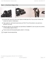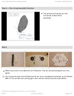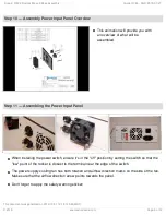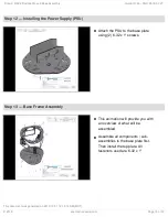
Step 14 — Install AC Wiring
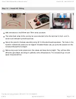
Add connectors to the 200mm and 75mm wires as shown.
The red & black wires for the cooling fan are connected to the first terminal in the V- and V+
sections as indicated by the blue arrows.
Secure the panel to the base assembly using (2) 10-32 socket head cap screws. The holes in the
injection molded side panels are not tapped / threaded. Make sure you put some pressure on the
screws and keep them straight.
Make sure you put some pressure on the screws and keep them straight. They will be a little
difficult to get started, but will go in perfectly with a little pressure. The screws will go in much
easier the second time.
Step 2. REV2 Rostock Max v3 Base Assembly
Draft: 2018-07-27
Guide ID: 66 -
This document was generated on 2019-10-01 12:14:14 AM (MST).
© 2019
seemecnc.dozuki.com/
Page 11 of 12


