background image


When an Alarm is entered, an “A” appears in the video which have 

received the alarm, in the place in which the channel loss is indicated.   


The Alarm input will not operate if an alarm signal is entered into a lost 

channel. 


-1. Alarm Input & Button Function 

In Alarm input mode or external data control model, you can only enter to the 

menu mode and other function button may not operate. During the Alarm Hold 
Time, press any button to escape from Alarm mode.   


-2. Alarm Input Cancel 

When the external control data or Alarm input is eliminated, it returns to the 

last  display  mode  which  has  been  displayed  before  the  external  data  has 
entered, after the Alarm Hold Time is ended. You can set the Alarm Hold Time 

in the Alarm Time menu in System/Display < SETUP MENU.   


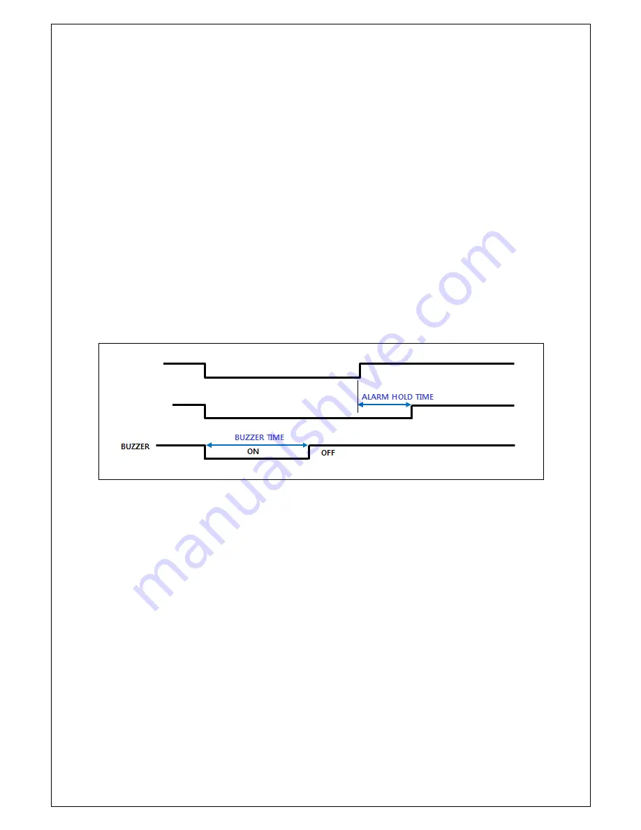
-3. Alarm Input Timing Structure 

When  the  Alarm  or  the  external  data  is  in,  the  screen  is  displayed  and  the 

buzzer operates as following timing diagram.   


The Alarm Hold Time is hold as long as the Buzzer Time last. (Alarm Hold 

Time = Buzzer Time)   


-4.    How to put the Alarm in 

Use a contact point signal such as switches or relay to Open/Short the Inx and 

the GND (Alarm Input port). Do not use any contact point with electrical signal. 
It may cause any malfunction of the device.   


-5 Alarm Output   

The  Alarm  output  provides  the  connect  point  to  activate  a  warning  lamp  or 

alarm bell when an alarm is entered.   


-6. Alarm Output Contact Point 

The Alarm output contact point is under Normal Open relay of 1A/24VDC, 0.5A 

/125 VAC.   


The relay may not activate properly when an overrated power is applied 

in the alarm output contact point. 


External 
Data IN 

External Data   
IN 

External Data OFF 

Screen Display 

Alarm INPUT 
mode 

Last 

Screen 

Display 

mode 

Содержание SC-04HDH

Страница 1: ...0 DIGITAL FULL HD SPLITTER SC 04HDS H User s Manual SC 04HDS H ...

Страница 2: ...o not use and or connect any devices inappropriate to the unit It may cause malfunction of the unit or fire Use this product under temperature conditions only between 0 C and 50 C Should be careful not to have the lines changed when connecting them Prior to turn on the device check the cable insulation condition of the data cable connected with external devices Before installing the product check ...

Страница 3: ...ys the date and time the name of channel on the monitor as well as when it occurs any channel loss 1 2 Features Displaying high resolution pictures and rapid image processing by the SOC chip Displaying video from 4 cameras at real time Auto sequence mode Motion Detect Automatic Transitions Pattern change detection function Supporting NTSC PAL system Displaying the date and time the name of the cha...

Страница 4: ...ss the single display button it freezes and unfreezes the video displayed in the screen To unfreeze the video press this button one more time In the menu mode it operates as ESC button In Freeze mode the LED indicator of Freeze button flickers MENU Press this button to display the Setup Menu in pop up mode SINGLE DISPLAY The left upper button displays the video of Ch1 the right upper button displa...

Страница 5: ... change the setup value 3 Ch1 Ch4 HD04 HD04 displays the same picture as the picture displayed through HDMI port 4 You can put out a single picture of 1 4CH or the picture entered through HDMI port through the Monitor output port 5 You can watch two equal pictures through two BNC F terminals of Monitor port HDMI Connect the HD High Definition Monitor with HDMI input port Serial Port Connect the RS...

Страница 6: ...A is available ALARM INPUT OUPUT Connect the alarm input output port to control the split display screen by a foreign sensor or switch connected Display mode per Foreign Alarm Input Foreign Input Display mode IN1 IN2 IN3 IN4 0 0 0 0 Normal Mode 1 0 0 0 CH 1 Full Display 0 1 0 0 CH 2 Full Display 1 1 0 0 CH 1 CH2 Dual Display 0 0 1 0 CH 3 Full Display 1 0 1 0 CH 1 CH3 Dual Display 0 1 1 0 CH 2 CH3 ...

Страница 7: ...splay SETUP MENU 3 Alarm Input Timing Structure When the Alarm or the external data is in the screen is displayed and the buzzer operates as following timing diagram The Alarm Hold Time is hold as long as the Buzzer Time last Alarm Hold Time Buzzer Time 4 How to put the Alarm in Use a contact point signal such as switches or relay to Open Short the Inx and the GND Alarm Input port Do not use any c...

Страница 8: ...en the Alarm Input port is produced a short circuit The relay maintains open when any external data is off or the alarm input is off after the alarm time is ended How to connect a warning lamp to the Alarm Output port RJ 45 Connect the Firmware Upgrade Input Power over 12VDC 500mA ...

Страница 9: ... 60Hz FORMAT NTSC PAL Selectable Screen splitting mode 1 2V 2H 4B 4R 4 OSD On Screen Display Inserting up to 16 characters alphabet and or numbers External Interface RJ 45 Firmware upgrade RS 232C RS 485 Connection port for external devices 14P T Block ALARM Input 4 8P Output 1 2P Serial Port 1 port of RS 485 2P Power Output DC 12V 300mA 2P POWER INPUT 2P Terminal Block over 12VDC 500mA Consumptio...

Страница 10: ... the below log in window appears The password in default is 1111 Please refer to the menu 5 5 1 on how to insert a password 5 1 Menu Structure In menu setting mode it is possible to set up system display channel and log in setting menu structure as below 5 2 System Setting In System setting it is possible to set up Language system ID and date and time display format Buzzer on off buzzer time ...

Страница 11: ...Menu Button buttons and then press ENTER button in System set and buttons Then press ENTER in System ID and buttons to change the set up value and select the number from 1 to 255 5 2 3 Date Display Format In this menu it is possible to set the date display format Press Menu press buttons and ENTER in System set press buttons and ENTER in date display format press buttons to change the set up value...

Страница 12: ...ons to change the value among 1 99 seconds 5 2 7 Default Set It is possible to initialize the value and the menu will be set to default mode Press Menu press buttons and ENTER in System set press buttons and ENTER in Default set select ENTER or ESC 5 3 Display Set In Display set it is possible to set Time Channel name Sequence time Video format NTSC PAL HDMI resolution HDMI display position Spot d...

Страница 13: ... Before setting please check the resolution of monitor If the resolution is set higher than the available specification the image may not be appeared on the screen In this case you must use the adequate monitor and change the configuration Press Menu press buttons and ENTER in Display set press buttons and ENTER in HDMI resolution Press and ENTER button to select the desired resolution Please canc...

Страница 14: ...Virtual keyboard Virtual keyboard Pop up window The current name appears on the upper side of Pop up window When the red cursor appears on the bottom of the character move the cursor and edit the name using the buttons image appeared in the pop up menu To move the character in the pop up window use the direction key Single Display button And then press ENTER button in virtual Keyboard to select th...

Страница 15: ...rn change detection function Select among Low Normal and High Using the front function button press the button to move the cursor press ENTER and then change the value pressing the Area Set Set the motion and or pattern change detection area CLEAR It cancels the selected detection setting area All It selects all as detection area Set You can set the detection area as you want To set the detection ...

Страница 16: ... Press Menu button buttons then press ENTER buttons in channel setup mode And then in alarm mode press ENTER buttons and select whether you want to use the alarm function or not 5 5 Login set In this menu it is possible to set the password use change password ...

Страница 17: ...able Press buttons to select whether you want to activate or deactivate the password 5 5 2 Password Change Use this menu to change the password Press Menu press buttons and ENTER in Login set press buttons and ENTER in Password change separate pop up window appears To change the password set Enable the Password Enable menu Choose the 4 digits using the camera select buttons 1 4 in front of the uni...

Страница 18: ...17 6 Connection Diagram ...

Страница 19: ... we give you free repair service according to the warranty certificate We charge you with the fee of parts and service despite of free warranty service period Any breakage made without care such as Breakage or trouble made by natural disaster Breakage or trouble made by breaking the product guide or manual Breakage or trouble made by wrong power voltage or frequency When you want to reassemble for...

Страница 20: ...0 06 6 S Su un ni il l T Te ec ch hn no op pi ia a 4 44 40 0 S Sa an ng gd da ae ew wo on n D Do on ng g J Ju un ng gw wo on n G Gu u S Su un ng gn na am m S Si i G Gy ye eo on ng gg gi i D Do o K Ko or re ea a T TE EL L 8 82 2 0 0 3 31 1 7 77 77 7 3 35 50 08 8 F FA AX X 8 82 2 0 0 3 31 1 7 77 77 7 3 35 51 12 2 E EM MA AI IL L o ov ve er rs se ea as s s ss sc cc ct tv v c co om m h ht tt tp p w ww...

Отзывы: