13
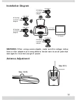
Setting up the Camera(s)
1)
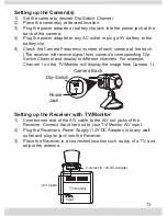
Set the camera to desired Dip-Switch Channel
2)
Place the camera(s) at desired location.
3)
Plug the power adapter or battery clip jack into the power jack at the
back of the camera.
4)
Plug the power adapter to any AC outlet or plug a 9V battery to the
battery clip.
5)
Check the Camera Frequency number of each camera at the back.
(The receiver will receive signal from camera’s corresponding Dip-
Switch Channel and display in different channels. For example,
Channel 1 on the TV/Monitor will display the image from Camera 1.)
Setting up the Receiver with TV/Monitor
1)
Connect one end of the A/V cable to the A/V out jacks of the
Receiver. Connect the other end to your TV/Monitor A/V input.
2)
Plug the Receiver’s Power Supply (12V DC Adapter) into any wall
outlet and plug its jack into the Receiver.
3) Place the Receiver in a convenient location such as top of a TV, and
adjust the antenna.
AUDIO/R
AUDIO/L
VIDEO/R
AUDIO/R
AUDIO/L
VIDEO/R
DC12V
TV/ Monitor
Input
Connect to 12V DC Adapter
A/V Cable
Camera Back
Dip-Switch
12
1
2
CH1 CH2 CH3 CH4
Power
Jack

