Security Tronix ST-IP-DVF-1 Скачать руководство пользователя страница 13


3  Network Configuration


The IP address of each camera is the same when leaving the SecurityTronix factory (default 

IP192.168.1.108). For the smoothest project installation, please allocate a useable IP segment of 

the entire network according to the actual network environment. 

3.1  Modify IP Address


IP address can be acquired and modified through the quick configuration tool for the cameras which is 

accessed via a wired network; Cameras must connect via a wired network to configure  wireless 

parameters before using wireless network cameras. This chapter will introduce the approach of 

modifying IP addresses via the “Quick Configuration Tool”. You can also modify the IP address in the 

network parameters of the WEB interface. Please refer to the document in the disk << WEB Operation 

Manual>> for more details. 

NOTE: 

Currently the quick configuration tool only supports cameras which are addressed within the same 

network segment (subnet) as the computer’s IP address. 

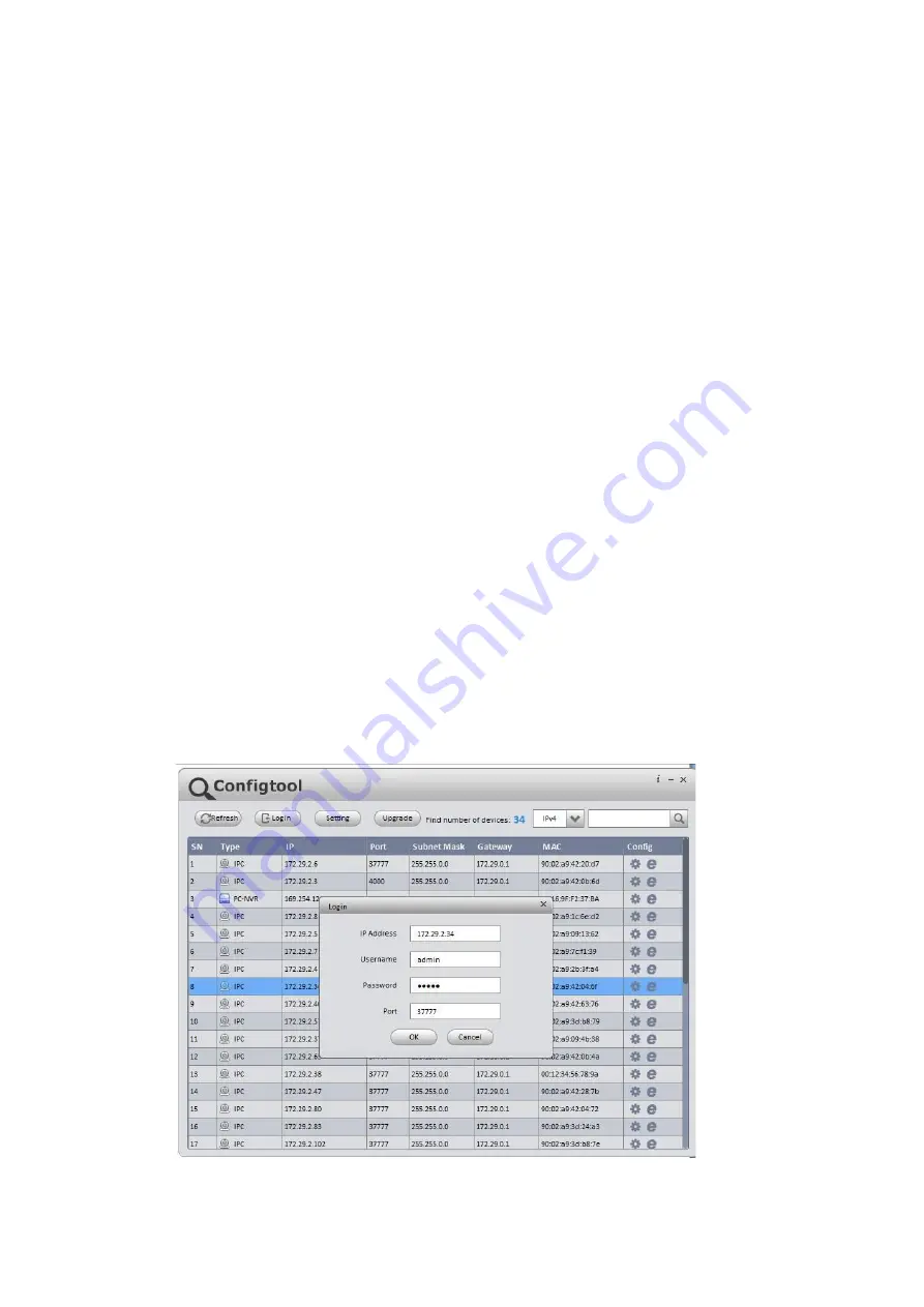
Step 1 Double click the “ConfigTools.exe” and open the quick configuration tool. 

Step 2 Double click the device to be configured, and the “Login” dialog box will appear. Enter the IP 

address, user name, password and port number of the camera, and click “Confirm”. 

NOTE: 

The default user name and password are admin and admin respectively. The default port number is 

37777.  See Figure 3-1 for more details. 


Содержание ST-IP-DVF-1

Страница 1: ...ST IP DVF 1 ST IP DVF 2 HD Mini Network Dome Camera Quick Start Guide Version 1 0 0 ...

Страница 2: ...pply to the camera at the same time it may result in camera damage We assume no liability or responsibility for fires or electrical shock caused byimproper handling or installation We are not liable for any problems caused by unauthorized modification or attempted repair 2 Environment Don t aim the camera at strong light such as lighting sunlight and so on to focus otherwise it may cause overexpos...

Страница 3: ...pe cover surface directly during installation and use please refer to the following methods to clean a dirty lens Stained with dirt Use an oil free soft brush to gently remove it Stained with grease or fingerprints Use a soft cloth to wipe the dome gently to dry it then use oil free cotton cloth or paper soaked with alcohol or detergent to wipe from the lens center to outward It is ok to change th...

Страница 4: ...user s manual and tool Before installation please open the package and check all the components areincluded Contact your local retailer ASAP if something is broken in your package Accessory Name Amount Network Camera Unit 1 Quick Start Guide 1 Installation Accessories Bag 1 CD 1 ...

Страница 5: ...1 Components 1 1 2 Physical Properties 2 1 3 Alarm Setup 3 2 Camera Installation 4 2 1 Installation Steps 4 2 2 Micro SD Card Installation 6 2 3 Lens Adjustment 7 3 Network Configuration 8 3 1 Modify IP Address 8 3 2 Login WEB Interface 9 ...

Страница 6: ...function may differ according to different models please refer to the actual camera for details 1 1 Components Refer to the following figure for hardware configuration See Figure 1 1 Figure 1 1 Component functions Please refer to the following sheet for detailed information Component Component Name Component 1 Dome camera module Component 2 Dome enclosure ...

Страница 7: ...upported by ST IP DVF 1 2 Port 7 Audio output port Output audio signal to speakers optional not supported by ST IP DVF 1 2 Please refer to the following sheet for detailed information about I Oport Port Name Port Sequence Port name Function Description I O Port 1 ALARM_IN1 Alarm input port receive on off signal of external alarm source 2 ALARM_OUT1 Alarm output port output alarm signal to alarm ca...

Страница 8: ...igure for alarm input information See Figure 1 3 Alarm input When the input signal is idle or grounded the camera can collect the different statuses of the alarm input port When the input signal is connected to 3 3V or idle the camera collects the logic 1 When the input signal is grounded the camera collects the logic 0 Figure 1 3 Please refer to the following figure for alarm output information S...

Страница 9: ...4 Different models may have different ways to install due to different appearance please refer to the corresponding figures according to the actual products Manual Vari focal Camera Figure 2 1 ...

Страница 10: ...ose plier or similar tool to pry out and remove the thin metal of the camera s outer shell as shown in Figure 2 1 above Remove this for surface cable use Step 4 Adjust the base of the camera to the proper position and then pull the cable through the cable exit hole drilled earlier in the ceiling or wall Line up the TOP direction of the device to the installation template and then line up the three...

Страница 11: ...e cover to the camera properly taking care to align the screws with the corresponding holes and fasten the three hex screws with the included hex wrench The camera installation isnowcomplete 2 2 Micro SD Card Installation Note This model of camera does not support Micro SD card functions Shut down the power and turn off the camera before you install the Micro SD card Step 1 Find the Micro SD Card ...

Страница 12: ...en move the threaded rod of adjustment screw D slightly to rotate the lens barrel it is connected to Make the lens focus clear according to the image display then tighten the adjusting screw D Step 3 The image may become blurry during the process of tightening adjusting screw D adjust the image slightly by moving adjusting screw C then adjust the image to become clear and finally tighten the screw...

Страница 13: ...e approach of modifying IP addresses via the Quick Configuration Tool You can also modify the IP address in the network parameters of the WEB interface Please refer to the document in the disk WEB Operation Manual for more details NOTE Currently the quick configuration tool only supports cameras which are addressed within the same network segment subnet as the computer s IP address Step 1 Double c...

Страница 14: ...interfaces the figures below are just for reference please refer to the document WEB Operation Manual in the disk and the actual interface for more details Step 1 Open IE and input the modified camera IP address in the address bar Step 2 The login interface is shown below please input your user name and password Default user name is admin and password is admin respectively click login See Figure 3...

Страница 15: ...gure 3 3 Step 3 Install controls according to the system prompt see Figure 3 4 for the WEB main interface Modify the administrator password as soon as possible after you have successfully loggedin Figure 3 4 ...

Страница 16: ...ice Please visit our website or contact your local service engineer for more information SecurityTronix offers live human tech support for our products 24 hours a day 7 days a week 365 days a year Technical support contact info Phone 610 688 9282 Option 3 then 2 Email support securitytronix com Web www securitytronix com support SecurityTronix 1085 Andrew Dr Ste A West Chester PA 19380 ...

Отзывы: