348
4.8.3.3 Network Test
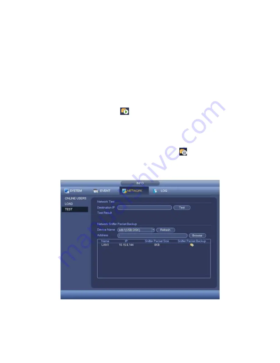
Network test interface is shown as in Figure 4-98.
Destination IP: Please input valid IPV4 address or domain name.
Test: Click it to test the connection with the destination IP address. The test results
can display average delay and packet loss rate and you can also view the network
status as OK, bad, no connection and etc.
Network Sniffer backup: Please insert USB2.0 device and click the Refresh button,
you can view the device on the following column. You can use the dropdown list to
select peripheral device. Click Browse button to select the snap path. The steps here
are same as preview backup operation.
You can view all connected network adapter names (including Ethernet, PPPoE, WIFI,
and 3G), you can click the button
on the right panel to begin Sniffer. Click the grey
stop button to stop. Please note system cannot Sniffer several network adapters at the
same time.
After Sniffer began, you can exit to implement corresponding network operation such as
login WEB, monitor. Please go back to Sniffer interface to click
stop Sniffer. System
can save the packets to the specified path. The file is named after “Network adapter
name+time”. You can use software such as Wireshark to open the packets on the PC for
the professional engineer to solve complicated problems.
Figure 4-98
4.8.4 Log
Содержание PENDVR-EL8M4K
Страница 1: ...PENDVR EL8M4K ELITE SERIES...
Страница 19: ...247 2 3 Connection Sample...
Страница 127: ...363 restore original status Figure 4 115 Figure 4 116 4 9 1 3 1Upgrade Camera...
Страница 150: ...386 Figure 4 137 Figure 4 138...
Страница 157: ...393 Figure 4 145 Step 2 Draw tripwire 1 Click Draw button to draw the tripwire See Figure 4 146 Figure 4 146...
Страница 161: ...397 Figure 4 149 Step 2 Draw the zone 1 Click draw button to draw the zone See Figure 4 150 Figure 4 150...
Страница 163: ...399 Figure 4 151 Step 2 Draw the zone 1 Click draw button to draw the zone See Figure 4 152 Figure 4 152...
Страница 165: ...401 Figure 4 153 Step 2 Draw the zone 1 Click Draw button to draw a zone See Figure 4 154...
Страница 171: ...407 Figure 4 157 Figure 4 158...
Страница 172: ...408 Figure 4 159 Figure 4 160...
Страница 173: ...409 Figure 4 161 Figure 4 162...
Страница 176: ...412 Figure 4 165 Figure 4 166...
Страница 177: ...413 Figure 4 167 Figure 4 168...
Страница 183: ...419 Figure 4 177 Figure 4 178 4 9 4 1 2 2 Trigger Snapshot...
Страница 185: ...421 Figure 4 180 Figure 4 181 4 9 4 1 2 3 Priority...
Страница 191: ...427 Figure 4 186 Figure 4 187...
Страница 196: ...432 Figure 4 193 Figure 4 194...
Страница 209: ...445 Figure 4 209 For digital channel the interface is shown as below See Figure 4 210 Figure 4 210...
Страница 216: ...452 Figure 4 218 Step 2 Click Add user button in Figure 4 218 The interface is shown as in Figure 4 219 Figure 4 219...
Страница 282: ...518 Figure 5 69 Figure 5 70...
Страница 298: ...534 device Figure 5 86 Figure 5 87...
Страница 304: ...540 Figure 5 94 Figure 5 95...
Страница 305: ...541 Figure 5 96 Figure 5 97 Please refer to the following sheet for detailed information...
Страница 309: ...545 Figure 5 101 Figure 5 102 Figure 5 103 Please refer to the following sheet for detailed information...
Страница 332: ...568 Figure 5 136 Note For admin you can change the email information See Figure 5 137...
Страница 362: ...598 448K 196M 512K 225M 640K 281M 768K 337M 896K 393M 1024K 450M 1280K 562M 1536K 675M 1792K 787M 2048K 900M...


