background image


15 

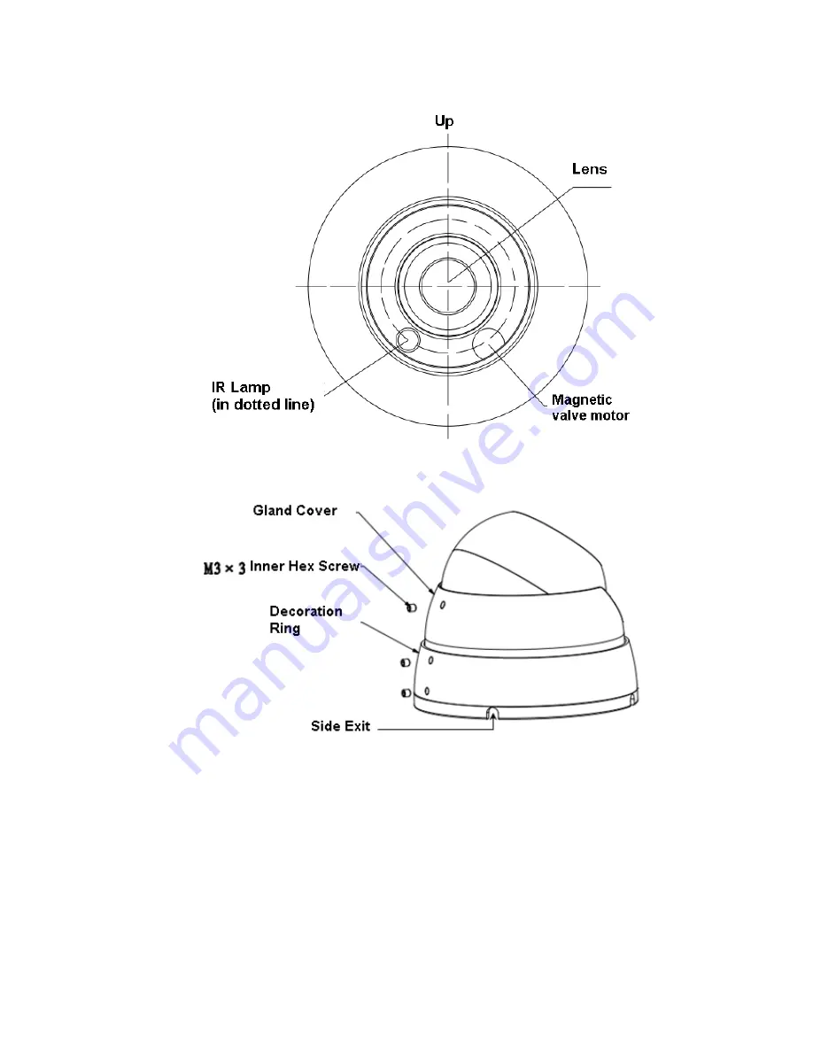
Please pay attention to the dome camera direction when you are installing. Please refer to the 

following figure for detailed information. See Figure 3-2. 


Figure 3-2 Device installation illustration 2 


Figure 3-3 Device installation illustration 3 


3.2


Installation Steps for Plastic Dome 

Please follow the steps listed below to install the device.  Please refer to Figure 3-4 for reference. 


Содержание IPOD-EL2IRE

Страница 1: ...IPOD EL2IRE User s Manual Version 1 3 3...

Страница 2: ...r Network camera This user s manual is designed to be a reference tool for your system Please read the following safeguard and warnings carefully before you use this series product Please keep this us...

Страница 3: ...n Please install the proper power cut off device during the installation connection Always follow the instruction guide the manufacturer recommended 4 Qualified engineers needed All the examination an...

Страница 4: ...not touch the enclosure when you are installing the device or clean the enclosure when you are doing maintenance work Please use professional optical clean method to clean the enclosure Improper enclo...

Страница 5: ...amework and Dimension 11 3 Device Installation 14 3 1 Installation Steps for Metal Dome 14 3 2 Installation Steps for Plastic Dome 15 4 Quick Configuration Tool 17 4 1 Overview 17 4 2 Operation 17 5 W...

Страница 6: ...t central server backup function in accordance with your configuration and setup in alarm or schedule setting Support record via Web and the recorded file are storage in the client end PC Support netw...

Страница 7: ...1 3 to 1 10000 Video Compression Standard H 264 H 264B MJPEG Video Frame Rate PAL Main stream 1280 720 25fps extra stream 704 576 25fps NTSC Main stream 1280 720 30fps extra stream 704 480 30fps Vide...

Страница 8: ...ime network local record and remote operation at the same time User Interface Remote operation interface such as WEB DSS PSS System Status Bit stream statistics log and software version Video Paramete...

Страница 9: ...DDNS PPPOE IPv4 v6 QoS UPnP NTP HTTPS Bonjour Remote Operation Monitor system setup file download log information maintenance upgrade and etc Platform Interface Standard Support ONVIF General Paramet...

Страница 10: ...8mm 3 6mm 6mm Fixed focus Lens Interface M12 Lens is the default accessories Video Motion Detect 396 18 22 detection zones sensitivity level ranges from 0 to 100 area threshold ranges from 0 to 100 A...

Страница 11: ...576 20fps extra stream 2 1280 720 1fps Main stream 1920 1080 25fps extra stream 1 704 576 25fps extra stream 2 1280 720 11fps NTSC Main stream 1280 960 30fps extra stream 1 704 480 30fps extra stream...

Страница 12: ...nd PoE Note 05 series does not support PoE Power Consumption DC 12V 3 1W MAX DC 12V 3 6W MAX Working Temperature 30 60 Working Humidify 95 Dimensions mm 113 6 85 8 Weight 0 27kg Installation Ceiling a...

Страница 13: ...lip Support mirror Support flip function Snapshot Max 1f s snapshot File extension name is JPEG Privacy Mask Supports max 4 privacy mask zones Video Setup Support parameter setup such as bright contra...

Страница 14: ...05 series does not support PoE Power Consumption DC 12V 3 1W MAX DC 12V 3 6W MAX Working Temperature 30 60 Working Humidify 95 Dimensions mm 93 4 80 5 Weight 0 35kg Installation Ceiling and wall moun...

Страница 15: ...10 2 Structure 2 1 Components You can refer to the following figures for product appearance information See Figure 2 1 and Figure 2 2 Figure 2 1 Metal Dome Figure 2 2 Plastic Dome...

Страница 16: ...me devices do not support PoE 5 DC12V DC 12V power To connect to DC12V power supply 2 2 Framework and Dimension Please refer to the following two figures for dimension information The unit is mm See F...

Страница 17: ...12 Figure 2 4 Dimension of Metal Dome 2 Figure 2 5 Dimension of Plastic Dome 1...

Страница 18: ...13 Figure 2 6 Dimension of Plastic Dome 2...

Страница 19: ...requirements Draw and then dig four expansion bolts holes in the installation surface and then insert four expansion bolts in the holes Secure these four bolts firmly Please draw the cable out from t...

Страница 20: ...the following figure for detailed information See Figure 3 2 Figure 3 2 Device installation illustration 2 Figure 3 3 Device installation illustration 3 3 2 Installation Steps for Plastic Dome Please...

Страница 21: ...he holes Step 3 Adjust position of pedestal and aim the three holes on device pedestal at the three expansion bolts on installation surface Fasten the three self tapping screws into the three expansio...

Страница 22: ...n as in Figure 4 1 In the device list interface you can view device IP address port number subnet mask default gateway MAC address and etc Figure 4 1 Search interface Select one IP address and then ri...

Страница 23: ...o login Please note the port information here shall be identical with the port value you set in TCP port in Web Network interface Otherwise you cannot login the device If you are using device backgrou...

Страница 24: ...the PC and the network camera respectively Network camera default IP address is 192 168 1 108 Subnet mask is 255 255 255 0 Gateway is 192 168 1 1 Use order ping network camera address to check connect...

Страница 25: ...gin After you successfully logged in please install WEB plug in unit Please refer to the Web Operation Manual included in the resource CD for detailed operation instruction See Figure 5 3 Figure 5 3 W...

Страница 26: ...nstallation We recommend the win2000sp4 OS or install the client end of the low version The Active X control is blocked The display card version shall be dx8 1 or higher Network connection error occur...

Страница 27: ...toxic or hazardous substance or elements contained in products will not leak or mutate so that the use of these substances or elements will not result in any severe environmental pollution any bodily...

Отзывы: