Use these instructions in conjunction with the complete installation manual for
this product. Follow all warnings and directions specified within and/or on the
equipment.
You
must
complete
steps
1–4
before
powering
up
the
panel
.
Your SmartTech Dealer Portal:
cloud.secure.direct/smarttech/
Sign in using the dealer credentials provided by SecureNet Technologies.
You will now create a new “Customer/End-User” account. These steps can be used as
a checklist. Steps 1–4 are applicable for all panel types.
Create an Account
by expanding the “Accounts” section in the left side bar.
Select “Search Accounts” to access all accounts.
Select “Add Account” in the top right corner of the main “Accounts” list panel.
From the “Add Account“ screen, assign an Account ID and enter the basic account
information. To assign an account, choose one of two options:
Auto Assign - assigns the next available Account ID within your dedicated account
range. Manually Enter ID - enter the preferred account number in the “Account ID” field.
Set the Panel Type to “iotega”
All fields marked with an asterisk (*) are required. All details should be of the property
and master account contact. Site Phone may be set as a mobile.
Assign a Service Plan
that corresponds with the panel gateway type you are
installing (GSM, LTE, IP or WIFI).
Note: If more than one gateway is installed on the panel, select the service plan based
on cellular communication (GSM or LTE).
Otherwise, select the service plan based on the services provided:
l
Managed Alarm Transport (includes alarm signal forwarding only)
l
Interactive/Direct Alarm Transport (includes alarm signal forwarding, remote
arm/disarm, notifications, zone status, event history, panel offline
supervision)
l
Complete Interactive (includes all direct alarm transport features, plus Z-
Wave device support, scenes, event schedules, system sabotage
protection)
l
Direct Alarm Tra Video
l
Complete Inter Video
l
Stand Alone Video (Up to 4 cameras, 250 event storage & notifications)
l
Stand Alone Video Plus (Up to 8 cameras, 500 event storage & notifications)
Once the service plan is chosen, select “Next”.
If all required fields are complete, a “Complete” confirmation message is displayed.
Press “Finish” to add the account.
On the “Account Summary” page, select “Go Live!” to start services. This activates the
service functionality and starts billing.
Note: If you are creating the account in advance or wish to start services at a later
date, do not select “Go Live“ at this point. You can select “Go Live” at any time to begin
services.
Add a Gateway
by selecting “System” in the left side bar. On the “System” page,
select “Add Gateway” to bring up the “Add Gateway” panel.
Set the Panel Type to “iotega”
Enter the 10-digit ID number found on the bottom of the panel.
Press “Done” to add the gateway.
Create a Master Contact
by selecting “Contacts” in the left side bar. From the
“Contacts” page, select “Add Contact” and complete the form. All fields marked with an
asterisk (*) are required.
Assign a unique username and passcode for the customer to access both the end-user
website and mobile application.
The username must be between 3–32 characters long and can include alpha, numeric
or the ‘@’ (at), ‘_’ (underscore), ‘.’(period) characters.
The passcode must be between 6–16 characters and can contain only alpha or numeric
characters.
In the “Alarm User” section, set “User ID” to “Master” and enter the panel master code.
If you are installing a new panel, the default master panel access code
is “1234”.
Select “Done” to create the master contact. Following the initial system activation, the
contact information and panel codes can be edited from the “Contacts” page in both the
dealer portal and end-user customer web portals.
Note that only the master contact is created from the dealer portal. Additional user
contacts are created by the master account in the user portal.
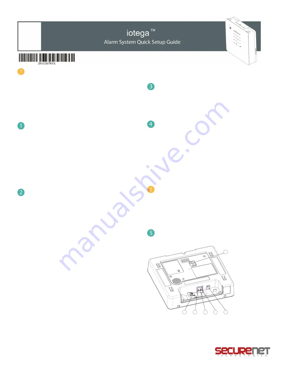
To Install the iotega
, locate the panel near the WiFi router during initial setup,
as direct connection via Ethernet cable is required.
5
4
3
2
1
6
1. Ethernet Cable Release
4. Ethernet Link Speed LED
2. Ethernet Link Activity LED
5. Power Connector
3. Ethernet Port
6. Case Tamper
Connect the Ethernet cable to the port on the back of the panel.
290010267R001
1


