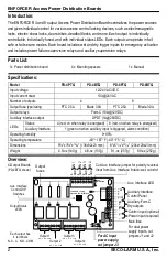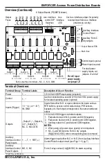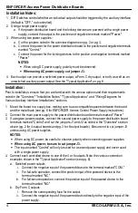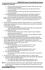
ENFORCER Access Power Distribution Boards
6
SECO-LARM U.S.A., Inc.
Typical Application:
N
C
C
N
O
C
O
M
NOTE:
Corresponding fuse must be
removed for this installation
+
–
+
–
NC
C
NO
Auxiliary
interface
control panel
NO C NC
INP
RET
T
–
+
–
+
Jumpers J1 and J2 cut for
dual power supply inputs
2
Access
control panel
output relay
NC NO C
Keypad
– +
NO COM
RTE
Plate
NO COM
DC Access
control power
supply
DC Access
control power
supply
(optional)
Control
Power
In
G
N
D
In
G
N
D
In
G
N
D
Electric
strike
(fail-secure)
Electromagnetic
door holder
Mag. lock
(fail-safe)
Mag. lock
(fail-safe,
form C)
N
C
C
N
O
C
O
M
N
C
C
N
O
C
O
M
N
C
C
N
O
C
O
M
1
3
4
2
1
3
4
– +
+
–
4
PD-4BTQ shown
3
2
1
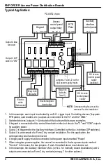
1.
In this example, each input is activated by an N.O. trigger input. Controlling devices' (keypads,
RTE plates, card readers, etc.) outputs are connected to the "In" and the "GND."
2.
Switched devices (outputs 1~4) include both fail-safe and fail-secure examples.
3.
A keypad is connected both to control the electric strike, but also to the "C" and "COM" outputs
for auxiliary power.
4.
Output 3 is triggered by the Auxiliary Interface (Controlled by the Aux. Interface DIP switches).
5.
Output 4 is an example of a Form C dry contact installation. For this application, the
corresponding fuse has been removed.
6.
A single power supply must be connected to the power inputs marked "Power."
7.
When using two power supplies, the second is connected to the two power inputs marked
"Control." In this case, the two jumpers J1 and J2 marked above must also be cut.
8.
In this example, the Auxiliary Interface's N.O. (or N.C. for normally closed installations) and C
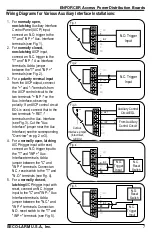
outputs are connected as Form C dry contacts (see pg. 7 for other options).
Output 4 fuse
removed
ON
OFF
1 2 3 4
AUX INTERFACE
J1
J3
J2
– +
– +
+ –
+ –
Output 3 DIP
switch is "ON"


