ENFORCER Access Power Distribution Boards
4
SECO-LARM U.S.A., Inc.
Installation Notes:
Installation:
1.
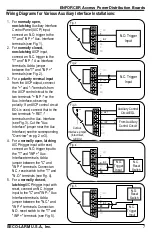
DIP Switches control whether an individual output should be triggered by the auxiliary interface
(default is "OFF," not controlled).
2.
Using a single power supply:
a.
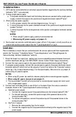
If the power distribution board and the locking devices are powered with a single power
supply, connect the output to the positive and negative terminals marked "Power."
3.
When using two power supplies:
a.
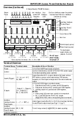
Cut the jumpers noted in the overview diagrams on pg. 2 or pg. 3.
b.
Connect the power for the power distribution board to the positive and negative terminals
marked "Control."
c.
Connect the power for the locking devices to the positive and negative terminals marked
"Power."
NOTES:
•
When using DC power supply, polarity must be observed.
•
When using AC power supply, cut jumper J3.
4.
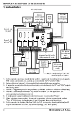
Each output can provide a switched power output, a Form C dry output, or both, as well as an
unswitched auxiliary power output. See the "Typical Application" on pg. 6.
Prior to installation, ensure that you are familiar with the various options and their requirements
noted in the "Overview," "Installation Notes," "Typical Application," and "Wiring Diagrams for
Various Auxiliary Interface Installations" sections.
1.
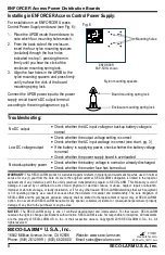
Mount the board in a supply box, making sure to use compatible spacers between the board
and the metal back (see pg. 8 for ENFORCER Access Control Power Supply instructions).
2.
Connect the main power supply to the power distribution board terminals marked "Power."
3.
If using two power supplies, connect the second power supply to the power distribution board
terminals marked "Control" and cut the jumpers J1 and J2 as noted in the "Overview" section
above (pg. 2 for 4-output boards and pg. 3 for 8-output boards). Be sure not to cut jumper J3
unless using AC power supplies.
NOTES:
•
When using DC power, be careful to observe polarity when connecting power supplies.
•
When using AC power, be sure to cut jumper J3.
•
The input marked "Control" will only be used for a second power supply and never used
with a single power supply.
4.
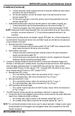
Connect each controlled device to one of the 4 or 8 outputs. Note the various connection
examples shown in the "Typical Application" section (see pg. 6).
a.
Switched power outputs
i.
Connect the negative input of the powered device to the terminal marked "COM."
ii.
For fail-safe operation, connect the positive input of the powered device to the
terminal marked "NC."
iii.
For fail-secure operation, connect the positive input of the powered device to the
terminal marked "NO."
b.
Dry Form C outputs
i.
Remove the corresponding fuse for the output.
ii.
Connect the negative input of the powered device directly to the negative input of the
power supply.


