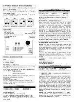
B) AUT / S-S ( Pre-flashing / Courtesy Light ) :
The control unit is supplied by the manufacturer with Pre-
flashing and Courtesy Light functions disabled. If you wish to
enable the Pre-flashing function, proceed as follows: make sure
that you have enabled Extended Menu 2 (T. PAUSA LED and
RIT. ANTE LED start flashing simultaneously), with the SEL key
positioned on the flashing of AUT/ S-S LED then press the SET
key, the AUT/S-S LED will simultaneously stays on steadily and
programming is completed. If you wish to enable the Courtesy
Light, repeat the operation described above, pressing the SEL
button twice instead of once (the AUT / S-S LED will flash
rapidly). Repeat the operation to restore the initial configuration.
Pre-flashing** function
The flashing beacon 230 Vac is always
activated 3 seconds before the automation starts any type of
motion.
Courtesy Light Function:
The Flashing beacon 230 Vac
output will be activated for 3 minutes, each time that an opening
command is given.
C) CODE ( Flashing beacon function ) :
The control unit is supplied by the manufacturer with the
flashing beacon function during the Pause Time disabled. If you
wish to enable the function, proceed as follows: make sure that
you have enabled Extended Menu 2 (T. PAUSA LED and RIT.
ANTE LED start flashing simultaneously), with the SEL key
position on the flashing of CODE LED then press the SET key,
the CODE LED will simultaneously stay on steady and
programming is completed. Repeat the procedure to restore the
previous configuration.
D) INB. CMD. AP. LED ( SOFT START ) :
The control unit is supplied by the manufacturer with the Soft
Start function disabled. If you wish to enable the function,
proceed as follows: make sure that you have enabled Extended
Menu 2 (T. PAUSA LED and RIT. ANTE LED start flashing
simultaneously), with the SEL key position on the flashing of
INB.CMD.AP LED then press the SET key, the INB.CMD.AP
LED will simultaneously switch on permanently and
programming is completed. Accordingly, every time the gate
starts motion the control unit will control motor start-up,
increasing the power gradually from minimum to maximum in
the first two seconds of operation. Repeat the procedure to
restore the previous configuration.
E) T. MOT. (Electric Lock activation CMD PED.) :
The control unit is supplied by the manufacturer with the
activation of the electric lock through the disabled Pedestrian
command. If you wish to enable the function, proceed as
follows: make sure that you have enabled Extended Menu 2 (T.
PAUSA LED and RIT. ANTE LED start flashing simultaneously),
with the SEL key position on the flashing of T.MOT. LED then
press the SET key, the T.MOT. LED will simultaneously switch
on permanently and programming is completed. The activation
of the electric lock function through the Pedestrian command, is
used when you have, for example, a sliding gate with a door
next to the Pedestrian passage. Accordingly, the gate can be
opened with the PUL commands as well as from the Pedestrian
door using the electric lock with the PED. commands for 2
seconds. Repeat the procedure to restore the previous
configuration.
F) T. MOT. PED. LED ( PUL and PED command functions ) :
The control unit is factory supplied with PUL control input
operation for the connection of a cyclical primary control button
(NA) and a PED input for the connection of a cyclical Pedestrian
command button (NA). If you wish to select another mode of
function of the PUL and PED inputs, proceed as follows: make
sure that you have enabled Extended Menu 2 (T. PAUSA LED
and RIT. ANTE LED start flashing simultaneously), by using the
SEL key select the flashing T. MOT. PED. LED and press the
SET button: T. MOT. PED. LED stays steadily lit and
programming is complete.
Accordingly, the PUL input makes it possible to connect a
button (NA) for the Opening phase only, and the PED input for
connection to a button (NA) for the Closing phase only. Repeat
the procedure to restore the previous configuration.
EXTENDED MENU 3
The control unit is supplied by the manufacturer with only the
option of directly selecting the functions listed in the main menu.
To enable power programming functions for deceleration
carried out by the control unit, proceed as follows: open
Extended Menu 2 (as instructed in the respective section), then
press and hold the SET key for 5 seconds, after which the T.
PAUSA LED and RIT. ANTE LED will start flashing alternately
and then simultaneous, in this way there will be 30 seconds to
select the desired deceleration using the SEL and SET keys,
then, after a further 30 seconds, the control unit returns to the
main menu.
---------------------- EXTENDED MENU 3 -----------------
Level Leds On
1 1-2 MOTORS
2 1-2 MOTORS - AUT / S-S
3 1-2 MOTORS - AUT / S-S - CODE
4 1-2 MOTORS - AUT / S-S – CODE - INB. CMD. AP.
5 1-2 MOTORS - AUT / S-S – CODE - INB. CMD. AP - T. MOT.
6 1-2 MOTORS - AUT / S-S - CODE - INB. CMD. AP - MOT. T. - PED. MOT. T.
Programming Motor Power during Deceleration
The control unit allows you to programme the motor power to
which the deceleration phase will be carried out.
It is possible to choose between 6 different levels of power:
every combination of lit Leds corresponds to a level according
to the table above; in other words, starting from the lowest led
(1-2 MOTORS LED) and moving upwards, each Led
corresponds to a higher power level. Using the SEL key it is
possible to scroll through the different power levels; for every
selected power level, the highest respective LED will flash (for
example, if level 4 is selected the 1-2 MOTORS AUT/S-S and
CODE LEDs light up steady, whereas the INB CMD. AP LED
flashes); press SET to confirm.
Level 3 is selected in the default configuration.
RESET :
To reset the default configuration of the control unit, press the
SEL and SET buttons simultaneously; all
RED
signal Leds will
switch on and then immediately off again.
DIAGNOSTICS :
Photocell Test :
The control unit is designed for the connection of safety devices
that comply with point 5.1.1.6 of standard EN 12453. With every
operation cycle, it performs a test of the operating photocells
connected. If there is no connection and/or non operation, the
control unit does not enable gate motion, and will visually report
the failed test by simultaneously flashing all of the LED signal
lights flash. Once the photocells are running correctly again, the
control unit is ready for normal operation. This ensures
monitoring against failures, in compliance with EN 954-1,
Category 2.
Содержание LG 2212 New
Страница 8: ...Rev 3 3 del 15 12 2020 ...
Страница 18: ...Rev 3 3 dated 15 12 2020 ...
Страница 28: ...Rév 3 3 du 15 12 2020 ...
Страница 39: ...Rev 3 3 vom 15 12 2020 ...
Страница 50: ...Rev 3 3 del 15 12 2020 ...
Страница 61: ...Rev 3 3 de 15 12 2020 ...
Страница 72: ...Αναθ 3 3 της 15 12 2020 ...

