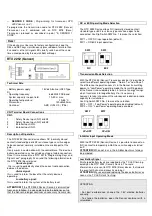
SENSOR 2 ( Operating logic RTX 2278 Sensor 2 ) :
The control unit enables connection of wireless safety devices
in accordance with Directive EN 12453.
The control unit is factory supplied with the following operating
logic installed for Sensor 2 operation: when it is triggered, it
causes the gate to stop and change direction briefly in both
opening and closing phases, if, naturally, module RTX 2278 is
installed on the control unit.
Opening and Closing Limit Switch:
The control unit allows the Opening and Closing Limit Switch
connection (NC). When it is triggered during the respective
operating phases, movement stops immediately.
Warning: Leave these inputs free if not used.
Adjusting Power and Initial Surge:
The electronic control unit is equipped with a "POWER "
trimmer to adjust motor Power and Speed, fully managed by the
microprocessor. The adjustment can be made within a range of
50% and 100% of the Maximum Power.
Nevertheless, every movement has an initial surge, powering
the motor for 2 seconds at the maximum power even if motor
power adjustment is enabled.
Warning:
You will need to repeat the Motor Time
programming procedure if you wish to adjust the "POWER",
as operation and deceleration times may be affected.
Obstacle detection:
( Valid only for LRX 2299 )
The electronic control unit is equipped with a "SENSITIVITY"
trimmer to adjust the Counter Power required to detect the
obstacle, fully managed by the microprocessor.
The adjustment can be made by setting a time interval
between a minimum of 0.1 seconds and a maximum of 3
seconds.
Note:
by setting the "SENSITIVITY" trimmer at the minimum,
the obstacle detection function is excluded.
Warning:
- During the slowed motion phase the obstacle detection
function is always disabled.
- The obstacle detection function always causes motion
reversal during the closing phase (except in the last 5
seconds of operation, in which case it stops) and reversal for
2 seconds during the opening phase (except in the last 5
seconds of operations, in which case it stops).
Deceleration:
The motor deceleration function is used on the gates to stop
them from reaching their final position at a high speed in the
opening and closing phases.
The control unit allows deceleration to be programmed for the
desired points (before the gates are completely open or closed)
during Motor Timer programming (see Main menu). It is also
possible to select the motor power to which the deceleration
phase between 6 different levels of power is carried out (see
Extended menu 3). The intermediate level is set during factory
configuration.
Warning light :
The control unit enables connection of a 24Vdc light to view the
status of automation. Light: off, automation closed; on, open;
slow flashing, opening motion; fast flashing, closing motion.
Flashing beacon function:
The electronic control unit is equipped with an output for the
management of the flashing beacon 230 Vac. Its function is
conditioned by motor motion and automatic closing which if
activated, enables the flashing beacon even during pause time.
Operation with TIMER:
The control unit can have a timer set up instead of an open-
close ( PUL ) control button.
Example: at 08:00 the timer closes the contact and the control
unit opens the gate. At 18:00 the timer opens the contact and
the control unit closes the gate. During the interval between
08:00 and 18:00, at the end of the opening phase, the control
unit disables the flashing beacon, automatic closing and radio
controls.
PROGRAMMING :
SEL key:
selects the type of function to be stored, selection is
indicated by a flashing LED.
Repeatedly press the key to select the desired function. The
selection remains active for 10 seconds, (indicated by the
flashing LED); after 10 seconds, the control unit returns to its
original status.
SET key:
this programs the information according to the type of
function previously selected with the SEL button.
IMPORTANT:
The function of the SET key can be replaced with the radio
control, if programmed previously (CODE led on).
MAIN MENU
The control unit is supplied by the manufacturer with the
possibility of selecting a number of important functions.
---------------------- MAIN MENU -----------------
LED Reference LED off LED On
1) 1-2 MOTORS Automation 1 Motor Automation 2 Motors
2) AUT / S-S Automatic Step by Step
3) CODE No code Code entered
4) INB.CMD.AP Disabled Enabled
5) T. MOT. 30 sec. motor time Programmed time
6) T.MOT.PED. Mot. Time Ped. 10 sec. Programmed time
7) T. PAUSA No auto close With auto close
8) RIT. ANTE No gate delay. Programmed time
1) 1 – 2 MOTORS :
For ease of installation, the control unit has, by default, two
automations with 1 or 2 motors.
The control unit has, by default, typical operation of automation
with 1 motor (e.g. sliding gate). To enable, by default, operation
of an automation to 2 motors (e.g. gate with doors), proceed as
follows: press the SEL key until the 1-2 MOTORS LED flashes,
then press the SET button. At the same time, the 1-2 MOTORS
LED remains steady and the procedure is completed.
Repeat the procedure to restore the previous configuration.
With 1 Motor, if required, it is possible to have Motor 1 and 2
outputs in parallel to double the applicable load (one Motor up
to 1.5 HP).
2) AUTOMATIC / STEP BY STEP:
The default settings of the control unit have " Automatic "
operating logic enabled (AUT/S-S LED off), if you want to
enable the operating logic "Step by Step" (AUT/ S-S LED on), it
is necessary to enable it; use the SEL key to move to the
flashing AUT/S-S LED then press the SET key. AUT/S-S will
light up steadily. Repeat the procedure to restore the previous
configuration.
3) CODE:
(Radio control code)
The control unit can store up to 150 radio controls with different
fixed or rolling codes.
Programming.
The transmission code is programmed in the following way:
using the SEL key to move to the flashing CODE LED, at the
same time send the pre-selected code from the radio control
you wish to use; when the CODE LED stays on steadily,
programming is finished.
If all 150 available codes have been
memorised, by repeating the programming operation, all
programming LEDs will start to flash, indicating that it is not
possible to memorise any more codes.
Содержание LG 2212 New
Страница 8: ...Rev 3 3 del 15 12 2020 ...
Страница 18: ...Rev 3 3 dated 15 12 2020 ...
Страница 28: ...Rév 3 3 du 15 12 2020 ...
Страница 39: ...Rev 3 3 vom 15 12 2020 ...
Страница 50: ...Rev 3 3 del 15 12 2020 ...
Страница 61: ...Rev 3 3 de 15 12 2020 ...
Страница 72: ...Αναθ 3 3 της 15 12 2020 ...


