background image

Latest products and information available at www.sealite.com

8

Radio Controller

Timeout Mode

Default = Enabled, LOW

This menu is used to setup the LED high intensity timeout feature found in each light. 

The options include 

Enabled LOW, Disable

.

a.  Enabled LOW – The immediate LED intensity is selected via the LED Intensity menu, after Timer 

Duration the LED Intensity will revert back to the LOW setting

b.  Disable – The high intensity LED timeout is disabled. The LED intensity will be selected via the LED 

intensity menu.

Note:

 this menu will not be enabled if the selected operational mode is STANDBY

Timeout Duration

Default = 15 Minutes

This menu is only visible when the timeout Mode is enabled. This menu is used to select the timeout 
duration, the time before the LED intensity reverts back to its LOW intensity state. The timeout duration 
can be set from 1 minute to 60 minutes. 

LED Banks (Optional)

Sealite radio controlled lights can have the option of having multiple colours, in different LED banks. 

This menu is used to select which LEDs on the light should be used to flash the selected flash code. The 

options include; 

All LED Banks, LED Bank 1 Only, LED Bank 2 Only, LED Bank 3 Only,  

LED Bank 4 Only, Alternating 1, 2 & Cycle 1, 2, 3, 4.

a.  ALL LED Banks – All LED Banks are used when on.

b.  LED Bank 1 Only – LED bank 1 only is used when on. LED banks 2, 3 & 4 are always off.

c.  LED Bank 2 Only – LED bank 2 only is used when on. LED banks 1, 3 & 4 are always off.

d.  LED Bank 3 Only – LED bank 3 only is used when on. LED banks 1, 2 & 4 are always off.

e.  LED Bank 4 Only – LED bank 4 only is used when on. LED banks 1, 2 & 3 are always off.

f.  Alternating 1, 2 – LED bank 1 & 2 will alternate at the end of each flash sequence. The light will start 

by flashing using LED bank 1, then it will flash an entire sequence using LED bank 2, then LED bank 

1, and so on....

g.  Cycle 1, 2, 3, 4 – LED bank 1, 2, 3 & 4 will alternate at the end of each flash sequence. The light will 

start by flashing using LED bank 1, then it will flash an entire sequence using LED bank 2, then LED 

bank 3, then LED bank 4, then LED bank 1 and so on....

Note:

 this menu will not be enabled if the selected operational mode is STANDBY

Flare Path Setup

This menu is used when the lights are required to flash sequentially, in either direction in a channel. 

To use this setting each light in the group will need to set sequentially using Rotary Switch B.

•  On each light set the rotary switch to A=0 B=Set the first pair of lights = 0, next set of lights = 1, etc... 

If you have, more than 16 sets along the runway just continue the setting, e.g. D, E, F, 0, 1 this will 

allow all lights to continue the flare path

FORWARD Flare Path 

Each set of lights will sequence from 0 to F.

REVERSE Flare Path

Each set of lights will sequence from F to 0.

SYNCHRONISATION OVERRIDE Flare Path

Rotary Switch B will be ignored and all lights with the same flash code will syncronise.

Содержание Radio Controller System

Страница 1: ...Version 1 1 Radio Controller System Installation Operation Manual ...

Страница 2: ...test products and information available at www sealite com Version No Description Date Author Approved 1 0 Manual launch April 2016 J Dore M Nicholson 1 1 Flash Code Update April 2017 A Dixon M Nicholson ...

Страница 3: ...ation 8 LED Banks Optional 8 Flare Path Setup 8 Light Sensor 9 External Input 9 Battery Diagnostic 9 Controller Battery Voltage 9 Sending Commands 9 Using the Radio Control to activate the Radio Controlled System 10 Turn all the lights ON 10 Setup the lights to operate in DUSK till DAWN mode 10 Channel B only is to be HIGH Intensity but Channel A will remain in current configuration 10 Channel is ...

Страница 4: ...perate within the manufacturer s specifications The battery is protected from over charging within the circuit to ensure maximum battery life On darkness the microprocessor will initiate a program check and after approximately 1 minute begin flashing to the set code The Sealite Radio Controlled Lighting System works by using a hand held radio controller to activate and setup an entire port harbour...

Страница 5: ... power RF module The backlit LCD can be seen during day or night The straightforward menu makes it easy to operate The Sealite Radio Controller comes standard with an IP68 rated charging plug omni directional antenna and ON OFF switch It can also be optioned with an RS232 input The Radio Controller and charger come in an IP68 Pelican Case to protect it from the harsh environment to which it may be...

Страница 6: ... position It may be necessary to charge the Radio Controller before use Turning the unit On To turn the unit on lift the red missile cover and flick the switch The radio controller will take 5 seconds to start up and it may take up to 30 seconds for the imbedded RF Module to be configured before a command can be sent Charging the Radio Controller a Unscrew the protective cap from the charging port...

Страница 7: ...onment the ON OFF switch should be turned off DUSK till DAWN Operational Mode The light is turned on and off based on the light sensor internal to each light If the light is in the darkness it will turn on If the light is in daylight it will turn off Light Group This menu is used to select the current light group The light group of each light is selected via rotary switch A found on the bottom of ...

Страница 8: ...ED banks 2 3 4 are always off c LED Bank 2 Only LED bank 2 only is used when on LED banks 1 3 4 are always off d LED Bank 3 Only LED bank 3 only is used when on LED banks 1 2 4 are always off e LED Bank 4 Only LED bank 4 only is used when on LED banks 1 2 3 are always off f Alternating 1 2 LED bank 1 2 will alternate at the end of each flash sequence The light will start by flashing using LED bank...

Страница 9: ... mode after the diagnostic has been completed If the battery voltage is within operational range the light will turn off for 1 second flash once then turn off for 1 second If the battery voltage is low the light with turn off for 1 second flash twice then turn off for 1 second Controller Battery Voltage This menu displays the current battery voltage of the controller unit Any voltage above 7 2V is...

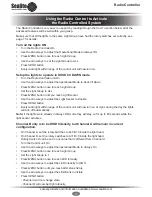
Страница 10: ... ALL Press MENU button until you reach Light Sensor Use the arrow keys to adjust the Light Sensor to Enable Press SEND button Every radio light within range of the control unit will now turn on at night during the day the lights will turn off automatically Note if the lights were already in Always ON mode they will stay on for up to 60 seconds while the light sensor activates Channel B only is to ...

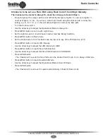
Страница 11: ...Mode to Always On Press MENU button once to reach Light Group Set the Light Group to 0 or whichever number matches Rotary Switch A Press MENU button to Flash Code Set the Flash Code to F 0 This flash code can be set to any of the 256 listed on p Press MENU button to reach LED Intensity Use the arrow keys to adjust the LED Intensity to HIGH Press MENU button to reach Flare Path Direction Use the ar...

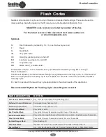
Страница 12: ...depends on the duty cycle i e the amount of time on as a proportion to the timing cycle For example 0 5 seconds on and 4 5 seconds off equals a 10 duty cycle It is best to operate at the lowest duty cycle appropriate to the actual needs of the application Recommended Rhythm for Flashing Light IALA Regions A and B MARK DESCRIPTION RHYTHM Port Hand Starboard Marks Any other than Composite Group Flas...

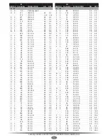
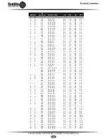
Страница 13: ... 5 S 0 3 2 2 B 4 180 FL 8 S 1 0 7 0 9 0 144 FL 2 5 S 0 5 2 0 6 2 98 ISO 8 S 4 0 4 0 D 6 214 FL 2 5 S 1 0 1 5 A 2 162 LFL 8 S 2 0 6 0 1 5 21 FL 3 S 0 2 2 8 6 6 102 OC 8 S 5 0 3 0 A 0 160 FL 3 S 0 3 2 7 294 OC 8 S 6 0 2 0 2 5 37 FL 3 S 0 4 2 6 B 2 178 LFL 8 S 3 0 5 0 B 0 176 FL 3 S 0 5 2 5 F 5 245 FL 9 S 0 9 8 1 3 5 53 FL 3 S 0 6 2 4 C 4 196 FL 9 S 1 0 8 0 C 0 192 FL 3 S 0 7 2 3 7 6 118 OC 9 S 6 0 3...

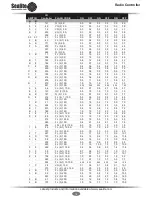
Страница 14: ...1 0 1 0 3 0 3 9 57 Q 2 6 S 0 3 0 7 0 3 4 7 295 LFL FL 6 S 3 0 1 0 1 0 1 0 273 FL 2 6 5 S 0 5 1 0 0 5 4 5 283 FL 2 7 S 0 4 1 2 0 4 5 0 311 FL 2 7 S 0 5 1 5 0 5 4 5 A 9 169 FL 2 7 S 1 0 1 0 1 0 4 0 7 B 123 FL 2 8 S 0 4 0 6 2 0 5 0 8 A 138 FL 2 8 S 0 4 1 0 0 4 6 2 285 FL 2 8 S 0 4 1 7 0 4 5 5 4 7 71 FL 2 8 S 0 5 1 0 0 5 6 0 297 FL 2 8 S 0 5 0 5 1 5 5 5 8 8 136 FL 2 8 S 0 8 1 2 2 4 3 6 5 7 87 FL 2 8 S...

Страница 15: ...1 0 B B 187 Q 3 10 S 0 3 0 7 0 3 0 7 0 3 7 7 D 8 216 FL 2 1 10 S 0 5 0 5 0 5 0 5 1 5 6 5 288 FL 3 12 S 0 4 2 1 0 4 2 1 0 4 6 6 1 B 27 FL 3 12 S 0 5 1 5 0 5 1 5 0 5 7 5 E A 234 FL 3 12 S 0 5 2 0 0 5 2 0 0 5 6 5 E 7 231 FL 3 12 S 0 8 1 2 0 8 1 2 0 8 7 2 B 6 182 FL 3 12 S 1 0 1 0 1 0 3 0 1 0 5 0 4 8 72 FL 2 1 12 S 0 8 1 2 0 8 2 4 0 8 6 0 5 8 88 FL 2 1 12 S 1 0 1 0 1 0 4 0 1 0 4 0 272 FL 3 12 5 S 0 5 ...

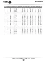
Страница 16: ... 7 0 3 1 7 0 3 5 7 4 F 79 FL 4 12 S 0 5 0 5 0 5 0 5 0 5 0 5 0 5 8 5 C E 206 FL 4 12 S 0 5 1 5 0 5 1 5 0 5 1 5 0 5 5 5 3 D 61 FL 4 12 S 0 8 1 2 0 8 1 2 0 8 1 2 0 8 5 2 A D 173 Q 4 12 S 0 3 0 7 0 3 0 7 0 3 0 7 0 3 8 7 4 D 77 FL 4 15 S 0 5 1 5 0 5 1 5 0 5 1 5 0 5 8 5 8 E 142 FL 4 15 S 1 0 1 0 1 0 1 0 1 0 1 0 1 0 8 0 7 D 125 FL 4 15 S 1 5 0 5 0 5 0 5 0 5 0 5 0 5 10 5 D E 222 FL 4 16 S 0 5 1 5 0 5 1 5 ...

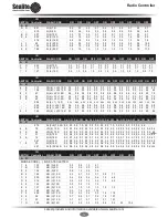
Страница 17: ... 95 292 FL 6 LFL 15 S 0 4 0 8 0 4 0 8 0 4 0 8 0 4 0 8 0 4 0 8 0 4 0 8 2 0 5 8 262 FL 6 LFL 15 S 0 5 0 5 0 5 0 5 0 5 0 5 0 5 0 5 0 5 0 5 0 5 0 5 2 0 7 0 8 F 143 VQ 6 LFL 15 S 0 3 0 3 0 3 0 3 0 3 0 3 0 3 0 3 0 3 0 3 0 3 0 3 2 0 9 4 SWITCH IR Controller FLASH CODE ON OFF ON OFF ON OFF ON OFF ON OFF ON OFF ON OFF ON OFF ON OFF A B 275 FL 3 5 12 2 S 0 9 0 3 0 9 1 0 0 9 0 3 0 3 0 3 0 3 1 0 0 3 0 3 0 3 0...

Страница 18: ...ure solar module is clean and not covered by shading during the day Lanterns are constantly on during the day Ensure the Rotary Switches are not set to F F This flash code is for testing purposes only and will be steady on for 24 hours a day Ensure the lights are not set to Always ON through the Radio Controller Set this to Dusk till Dawn for operation during night time only Lanterns are not synch...

Страница 19: ...nd workmanship under normal and intended use subject to the conditions hereinafter set forth for a period of twelve 12 months from the date of purchase by the original purchaser 5 Sealite Pty Ltd warrants that any LED sign lighting products Sign Lighting Products will be free from defective materials and workmanship under normal and intended use subject to the conditions hereinafter set forth for ...

Страница 20: ...ed by the incorrect replacement of battery in solar lantern models 11 This warranty does not cover any damage or defect caused to any product as a result of water flooding or any other acts of nature 12 There are no representations or warranties of any kind by Sealite or any other person who is an agent employee or other representative or affiliate of Sealite express or implied with respect to con...

Страница 21: ...Latest products and information available at www sealite com 21 Radio Controller Notes ...

Страница 22: ...hts Area Lighting Monitoring Control Systems Marine Buoys up to 3mt in diameter Mooring Systems Accessories Sealite United Kingdom Ltd UK t 44 0 1502 588026 Sealite Asia Pte Ltd Singapore Sealite USA LLC USA t 65 6829 2243 t 1 603 737 1311 Sealite Pty Ltd Australia t 61 0 3 5977 6128 We believe technology improves navigation info sealite com sealite com ...

Отзывы: