background image

ATLANTIC 3000

3000mm Diameter Ocean Buoy 

Latest products and information available at 

www.sealite.com

25

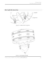
Mooring Bridle Assembly:-

STANDARD PIN SHACKLES

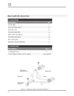
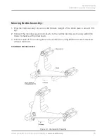
1.  Prop the bridle securely on some solid timbers (weight of the bridle plate is around 105 

kg).

2.  Connect the mooring swivel (not shown) to the central mooring point using a Ø44mm 

Grade S shackle with pin tail down.

3.  Connect each of the mooring links to the bridle arms using Ø44mm Grade S shackles 

with pin tail down.

Figure 10 - Standard D-Shackles

Содержание ATLANTIC-3000

Страница 1: ...1 ATLANTIC 3000 3000mm diameter Free Standing Polyethylene Ocean Buoy V1 0 INSTALLATION SERVICE MANUAL ...

Страница 2: ...2 Version No Description Date Author Approved 1 0 Manual Launch October 2018 G Percy G Percy ...

Страница 3: ...ations 5 ATLANTIC 3000 Ocean Buoy 6 Specifications 7 Assembly Instructions 8 Technical Drawings 8 Check Components 8 Central Float Collar Assembly 10 Tower Assembly 13 Tower Installation 17 Ladder and Top Mark Installation 19 Day Mark Installation 22 Mooring Bridle Assembly 24 Collar Replacement 30 Electronic Equipment Installation 31 Marine Buoy Maintenance 33 Notes 34 Warranty 36 Other Sealite P...

Страница 4: ...5 years and particular care has been taken to ensure your buoy gives years of service As a commitment to producing the highest quality products for our customers Sealite has been independently certified as complying with the requirements of ISO 9001 2015 quality management system By taking a few moments to browse through this booklet you will become familiar with the versatility of your buoy and b...

Страница 5: ...configurations and sizes and can be economically shipped worldwide Why Choose Polyethylene Buoys No painting Inhibits growth Increased interval between servicing Routine maintenance on location Easily repaired in the unlikely event of damage Lightweight for ease of deployment and maintenance Environmentally friendly no use of toxic antifouling paint Mooring Requirements Regulations Please contact ...

Страница 6: ...gher level of redundancy Ability to interchange colours to provide striped combinations such as IALA safe water or wreck marks Above the waterline the polyethylene tower is complemented by day panels to create a large visual area for improved recognition at distance 10TN Safe Working Load Large integrated lifting and mooring eyes offer a safe working load of up to 10T 2 eye lift which is comparabl...

Страница 7: ...s 10000 22046 Submergence kg cm lb inches 63 3523 5 Visual Area m2 ft2 5 9 631 2 7 2 777 10 with day marks Water Area m2 ft2 1 3 14 Physical Characteristics Material Rotationally moulded UV stabilised virgin polyethylene 316 grade internal tie bars lifting mooring eyes Wall Thickness mm inches 18 0 70 core 11 0 43 collars Ballast kg lbs 500 1102 internal concrete Filling Closed cell polyurethane f...

Страница 8: ...8 Technical Drawings ...

Страница 9: ...ATLANTIC 3000 3000mm Diameter Ocean Buoy Latest products and information available at www sealite com 9 Technical Drawings ...

Страница 10: ...oat Collar Assembly Float and Collars Description Qty Central Float 1 Float Collars 8 M16 x 80mm Long SS Bolt 24 Ø16 x 50 SS Flat Washer 48 Ø16 SS Spring Washer 24 M16 SS Plain Nut 24 Please read all steps before commencing Exercise care when handling buoy components in particular take care not to puncture scrape or otherwise damage polyethylene parts Assembly Aids Description Qty M10 x 45 Bolt 16...

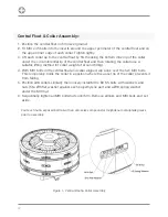
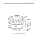
Страница 11: ...ATLANTIC 3000 3000mm Diameter Ocean Buoy Latest products and information available at www sealite com 11 Figure 1 Central Float Collar Assembly ...

Страница 12: ... of around 60Kg 4 With M10 bolts in the central float and collar aligned slip a link over the two M10 bolts This temporarily holds the collar in a position where the upper lip of the collar prevents it from falling 5 Position all 8 collars similarly then loosely install M16 x 80 SS bolts with washers and nuts fit a Ø16 flat washer against each polyethylene part and a Ø16 spring washer under the M1...

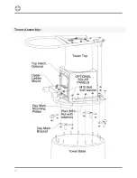
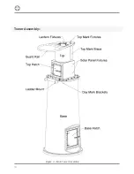
Страница 13: ...embled with guard rail top mark mounting plate top mark brace SS hatch option power pack option 1 Upper Ladder Mount Plate 4 fixing holes 1 Ø10 x 31 SS Flat Washer 14 Ø10 SS Spring Washer 14 M10 SS Plain Nut 14 Day Mark Fixings Description Qty Day Mark Mounting Plate with 3 mounting holes 2 Day Mark Mounting Plate with 4 mounting holes 2 Day Mark Bracket with Spiggot 4 M10 x 25 SS Bolt 8 Ø10 x 31 ...

Страница 14: ...14 Tower Assembly ...

Страница 15: ...holes over the exposed M10 bolt tails under the guard rail hoop ladder mounting lugs should be pointing down 5 Place an M10 flat washer and spring washer over each M10 bolt tail 14 places Coat each nut exposed bolt tail with an anti seize compound or molybdenum disulphide grease 6 Fit an M10 nut over each of the exposed M10 bolt tails and tighten until firm 7 If day marks are to be installed then ...

Страница 16: ...16 Tower Assembly Figure 4 Main Tower Assembly ...

Страница 17: ...loat flange There is a 110mm wide bump on the outside edge of each plate which should be positioned over one of the central float webs The flange plate doesn t have a top or bottom however all four plates should be oriented in the same way 3 Carefully lift the tower assembly onto the middle of the float assembly the weight of the tower assembly will be around 110 130 kg The hatch location in the b...

Страница 18: ...all tail down through holes in the main tower flange and mating holes in the float tower flange Coat each bolt tail with an anti seize compound or molybdenum disulphide grease 5 Fit a Ø12 flat washer Ø12 spring washer and plain M12 nut to each of the bolts Tighten until firm Figure 5 Tower Installation ...

Страница 19: ...lugs to the upper ladder mount plate Coat each bolt tail with an anti seize compound or molybdenum disulphide grease 2 Loosely fit a Ø10 flat washer Ø10 spring washer and plain M10 nut to each of the bolts 3 Likewise use two M10 bolts to attach the straight edge of the lower ladder mount plate to the angled lugs on the back of the bottom ladder rung and use another two M10 bolts to attach the curv...

Страница 20: ...20 Ladder and Top Mark Installation Figure 6 Ladder Installation ...

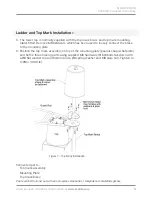
Страница 21: ...ct the brace to the mounting plate 6 Position the top mark assembly on top of the mounting plate peanut shaped flat plate and fix the three mating parts using supplied M8 hardware fit M8 bolts tail down with a Ø8 flat washer top and bottom and a Ø8 spring washer and M8 plain nut Tighten to 17 6Nm 13 0 ft lb Connected parts Top mark assembly Mounting Plate Top mark brace Coat each bolt tail and nut...

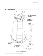
Страница 22: ... Align holes in the bottom beam of the day mark with holes in the adjacent tower flange plate 2 Fit a Ø12 flat washer to each of two M12 x 40 SS bolts and use to attach the bottom beam of the day mark to the tower flange plate install tail down Coat each bolt tail and nut with an anti seize compound or molybdenum disulphide grease 3 Fit a Ø12 flat washer Ø12 spring washer and plain M12 nut to each...

Страница 23: ...ATLANTIC 3000 3000mm Diameter Ocean Buoy Latest products and information available at www sealite com 23 Day Mark Installation Figure 8 Day Mark Installation ...

Страница 24: ...ooring Wear Bush 4 Mooring Link 2 M36 x 214 SS Bolt 2 Ø36 x 66 Flat Washer 2 M36 SS Slotted Nut 2 Ø6 Locking Pin 2 Ø44mm Grade S Shackle 3 Figure 9 Bridle Assembly Standard D Shackles Assembly Aids Description Qty Locking Pin Tool 1 Timber Props customer to supply As required ...

Страница 25: ...KLES 1 Prop the bridle securely on some solid timbers weight of the bridle plate is around 105 kg 2 Connect the mooring swivel not shown to the central mooring point using a Ø44mm Grade S shackle with pin tail down 3 Connect each of the mooring links to the bridle arms using Ø44mm Grade S shackles with pin tail down Figure 10 Standard D Shackles ...

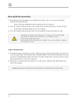
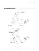
Страница 26: ...are welded shut 8mm circumferential fillet weld around head of pin 3 places 5 Turn the whole bridle assembly over weight of the bridle assembly is around 175 kg 6mm flush weld around tail end of pin 3 places 6 Turn the whole bridle assembly back over shackle pin heads should be on top 4 If the Ø44 Grade S shackles are of the safety pin type with nut and cotter pin then it is recommended that each ...

Страница 27: ...ATLANTIC 3000 3000mm Diameter Ocean Buoy Latest products and information available at www sealite com 27 Mooring Bridle Assembly Figure 11 Safety Shackles ...

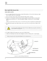
Страница 28: ...LT Lightly coat each bolt tail and nut with an anti seize compound or molybdenum disulphide grease 5 Fit a Ø36 flat washer and M36 slotted nut to each of the mooring bolts Tighten until firm 6 Fit a Ø6 locking pin through the hole in each M36 bolt tail 7 Using the locking pin tool bend the straight end of the locking pin to a right angle Do not over tighten the M36 mooring bolts Once assembled the...

Страница 29: ...ATLANTIC 3000 3000mm Diameter Ocean Buoy Latest products and information available at www sealite com 29 Mooring Bridle Assembly Figure 14 Mooring Bridle Installed Figure 13 Stainless Steel Locking Pins ...

Страница 30: ...be replaced and set aside 6 sets 5 Weight of each collar will be around 60Kg plus marine growth See Figure 1 While supporting the collar to be removed remove the link from the M10 bolts and lower the collar to the ground 6 Lift the replacement collar up to the central float by first hooking the bottom inner lip of the collar under the circumferential lip of the central float and then rotating the ...

Страница 31: ...rminal box in the battery boxes and install associated wiring Tie all cables in place using UV stabilized cable ties 3 Install and secure batteries in place using supplied battery clamps 4 Connect all negative and positive leads to the battery terminals Cover the terminals with a protective grease after connection and testing is finalised 5 Test the lantern by covering it with a dark cloth or jack...

Страница 32: ...32 Electronic Equipment Installation ...

Страница 33: ...movement of each swivel around its head If any swivel head sticks it must be replaced Check every link of the thrash length of the chain Check the diameter of the nips and sides and also inspect the welds on every link If depth allows a worn riding chain may be reversed Change a chain when any link shows excessive wear Chain must be replaced if any link wears to less than 3 5 of the original diame...

Страница 34: ...34 Notes ...

Страница 35: ...ATLANTIC 3000 3000mm Diameter Ocean Buoy Latest products and information available at www sealite com 35 ...

Страница 36: ...om the date of purchase by the original purchaser 2 Sealite Pty Ltd will repair or replace at Sealite s sole discretion any Buoy Products found to be defective in material and workmanship in the relevant warranty period so long as the Warranty Conditions set out below are satisfied Warranty Conditions This Warranty is subject to the following conditions and limitations 1 The warranty is applicable...

Страница 37: ...uct covered by this Warranty Sealite will not be liable to Buyer for consequential damages resulting from any defect or deficiencies Limited to Original Purchaser This Warranty is for the sole benefit of the original purchaser of the covered product and shall not extend to any subsequent purchaser of the product Miscellaneous Apart from the specific warranties provided under this warranty all othe...

Страница 38: ...Buoys up to 3mt in diameter Area Lighting Mooring Systems Accessories Sealite Pty Lty Australia 61 0 3 5977 6128 Sealite Asia Pte Ltd Singapore 65 6908 2917 Sealite United Kingdom Ltd UK 44 0 1502 588026 Sealite USA LLC USA 1 603 737 1311 We believe technology improves navigationTM sealite com info sealite com ...

Отзывы: