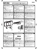
Fig.3
4.2 Assembling the end frames. Refer to Fig.1.
4.2.1 Attach a castor (E) into one end of each of the uprights (A1 & A2) using
bolts M10 x 20mm (J) and M10 nuts and spring washers (K).
Note: Ensure that the castors are attached in pairs for
each assembled frame, i.e. fixed castors on one frame and
swivel castors on the other.
4.2.2 Place the uprights (A1 & A2) on the floor with the inner edges
facing each other and the castors at the base.
4.2.3 Take one horizontal brace (B1) and one spacer (D). Insert into
the upright (A2) at the base area drilled hole and loosely
secure using a M6 x 50mm bolt (F) and a M6 nut (G).
4.2.4 Place the other upright (A1) so that the horizontal brace (B1)
aligns with the base area drilled hole. Take one of the diagonal
braces (C1) and insert into the upright (A1) so that the hole
aligns with the hole in the horizontal brace (B1) and the drilled
hole in the upright (A1). Loosely secure using a M6 x 50mm
bolt (F) and a M6 nut (G).
4.2.5 Align the other end of the diagonal brace (C1) with the
corresponding hole in the opposite upright (A2). Take another
diagonal brace (C2) and align with the same hole on diagonal
brace (C1) and on the upright (A2). Loosely secure using a M6
x 50mm bolt (F) and a M6 nut (G).
4.2.6 Align the other end of the second diagonal brace (C2) with the
corresponding hole in the opposite upright (A1). Take a second
horizontal brace (B2) and align with the second diagonal brace
(C2). Loosely secure both to the upright (A1) using a M6 x
50mm bolt (F) and a M6 nut (G).
4.2.7 Align the remaining end of horizontal brace (B2) with the
hole of the opposite upright (A2), insert a spacer (D) in the gap
and loosely secure using a M6 x 50mm bolt (F) and a M6 nut
(G). Place the last two horizontal braces (B3) together across
the top of the uprights (A1 & A2). Loosely secure using M6 x
50mm bolts (F) and a M6 nuts (G).
4.2.8 Check that the assembled frame is square and tighten all the
fasteners. Repeat the procedure for the second frame
assembly.
4.3 Fitting the cross beams. Refer to Fig.2.
4.3.1 Support one end frame in a vertical position and attach the end
of one cross beam (I) to it at the base of one of the uprights
(A). Ensure that both tags on the end bracket engage properly
with the slots in the upright as shown in the inset diagram. Tap
the cross beam gently next to the end bracket so that the
beam is properly seated into the slots in the upright. Insert the
safety bolt (H) so that it is against the beam and secure with a
M6 nut (G). Connect the other end of the beam to the second
end frame at the same height, tap into place and secure with a
safety bolt (H) and M6 nut (G).
4.3.2 Attach another cross beam (I) to the other side of the end
frames ensuring that it is at the same level as the first cross
beam.
4.3.3
See Fig.3.
Continue to assemble the next two pairs of cross
beams (I) at the heights required. The end frames allow
adjustment in 2" increments. Each pair of beams must be
mounted at the same height. Ensure that all tabs on the cross
beam brackets are fully engaged in the slots in the uprights
and that the cross beams are properly tapped down into place
then secured with a safety bolt (H) and a M6 nut (G).
NOTE:
It is our policy to continually improve products and as such we reserve the right to alter data, specifications and component parts without prior notice.
IMPORTANT:
No liability is accepted for incorrect use of this product.
WARRANTY:
Guarantee is 12 months from purchase date, proof of which will be required for any claim.
Fig.2
Parts support is available for this product.
To obtain a parts list and diagram please log on to www.sealey.co.uk, email [email protected] or phone 01284 757500
Environmental Protection
Recycle unwanted materials instead of disposing of them as waste. All tools, accessories and packaging should be
sorted, taken to a recycling centre and disposed of in a manner which is compatible with the environment.
When the product becomes completely unserviceable and requires disposal, drain off any fluids (if applicable)
into approved containers and dispose of the product and the fluids according to local regulations.