3. speciFicAtiOn
Model no:
.................................................................
sr2000
input power ..........................................................
230V 50Hz
input current .......................................................................
3A
output max. current .....................................................5000A
duty cycle: ...................................
100% @8~15 Al studs/min
consumables:
Al-mg studs pack of 10 .......................................sr2000.Am
Al-mg-si studs pack of 10 .................................sr2000.Ams
electrode kit ...........................................................sr2000.e
Pull washer pack of 10 ........................................
SR2000.PW
start washer pack of 10 ......................................
SR2000.SW
tabs pack of 10 ...................................................... sr2000.t
triangle washers .................................................
SR2000.TW
4. OperAtiOn
4.1.
general guidelines
4.1.1.
When welder is not in use switch off and disconnect from power supply.
4.1.2.
Welder must be switched off and disconnected from power supply for a minimum of 5 minutes before any maintenance is carried out
to ensure complete discharge of capacitors.
4.1.3.
Good contact between studs, tabs and the collet is required to ensure good welds. A loose fit will result in melting of the stud surface.
4.1.4.
Welding might cause welding arc and slight metal spatter so protective safety garments and eye protection are required at all times.
4.1.5.
Ensure there are no flammable materials or liquids in the work area.
4.1.6.
dO nOt
modify the cable or any part of the welding unit in any way.
4.2.
usage guidelines.
4.2.1.
ensure surfaces to be worked on are bare of all coatings, corrosion and grease.
4.2.2.
All welding components (studs, tabs, ground pins etc.) must be clean and corrosion free.
4.2.3.
ensure that adequate downward pressure is applied to the stud gun in use as good contact for both ground pins and welding
attachments is essential to the welding process. downward pressure adjustment is provided by altering the pre-load on the
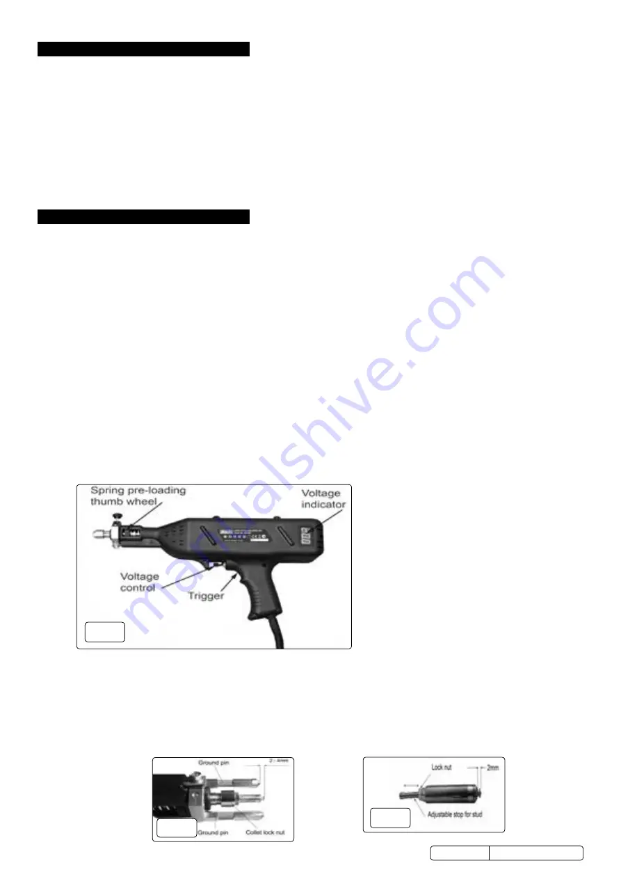
collet spring by rotating the thumb wheel in the barrel (fig.1).
4.2.4.
Voltage adjustment is provided by the rotating knob near the trigger. Voltage setting indication is provided by the LED display in the
stock handle of the welder.
4.3.
power settngs.
4.3.1.
For aluminium stud welding an initial voltage of 28 is recommended, adjusting up or down as required depending on weld results.
dO
nOt
make an adjustment of more than 3 volts at a time before re-testing.
4.3.2.
for steel tab welding an initial voltage of 22 is recommended, adjusting up or down dependant on results.
dO nOt
make an
adjustment of more than 3 volts at a time before re-testing.
wArning!
:
dO nOt
alter voltage settings rapidly in a short period of time as power must be allowed to dissipate from the welder.
frequent power changes in a short period of time will damage the unit.
4.4.
Stud welding fig.2, fig.3.
4.4.1.
disconnect equipment from power supply.
4.4.2.
in normal use the collet will wear and loosen its grip on the welding studs. this can be corrected by gently squeezing the jaws of the
collet together using a pair of pliers or an alternative form of controlled pressure.
dO nOt
hit with a hammer.
4.4.3.
Stud heads must protrude 2mm beyond the end of the collet (fig.3). Turn adjustable stop in and out to set stud height. The stud must
fit up against stop. Tighten lock nut to fix position.
4.4.4.
Install the two ground pins on opposite corners of the mounting plate (fig.2).
4.4.5.
Insert the collet into the collet holder. The flat surface
of the tip of the stud should extend 2-4mm past the tips o
f the ground pins(fig.2).
4.4.6.
Set power level as guided in section 4.3.
Original Language Version
© Jack sealey limited
fig.3
fig.2
fig.1
s
R2000 Issue 1 15/06/18


