


5.2.3
Before the blade can be removed release the tension on the blade by turning the blade
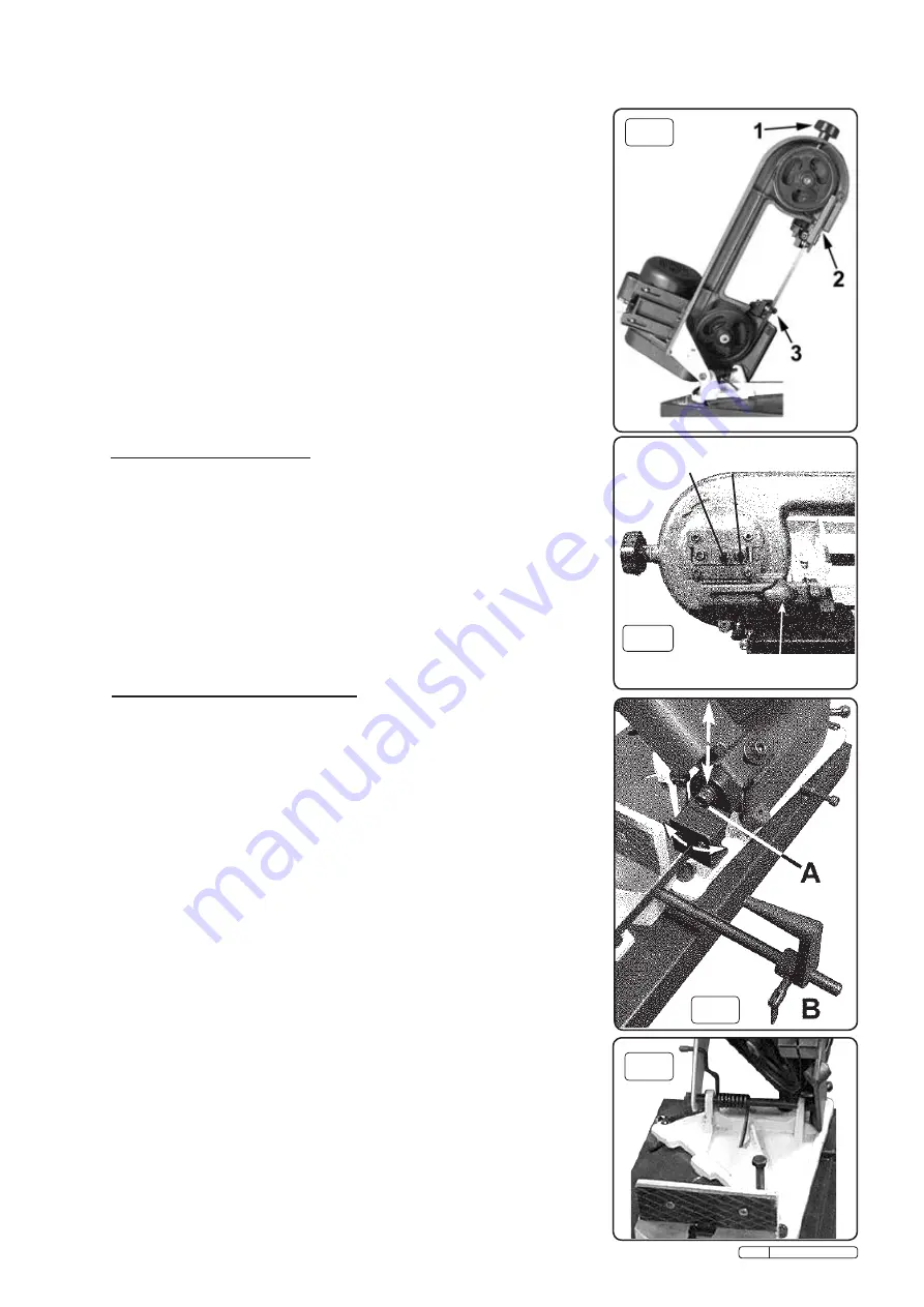
tension knob (fig.5 - 1) anticlockwise.
5.2.4
Remove the upper blade guide (2) which is held by a single hex socket cap screw.
5.2.5
Ease the blade away from the lowest pulley wheel first and support it as you remove it
from the upper pulley wheel then carefully remove the blade from between the guides.
5.2.6
Place the new blade through the guides first and then ease it around the lower pulley
wheel. (Ensure that the tooth direction is consistent with the blade travelling left to right in
the cutting area.) Retain the blade on the lower pulley with one hand and take up the
tension at the top of the blade with the other hand. Then use both hands to ease the
blade over the upper pulley.
5.2.7
Begin to tension the blade by turning the knob (1) clockwise but as you do so make sure
that the back edge of the blade is seated against the rim of both pulleys. Check that the
blade is seating properly by turning the upper pulley by hand
( using the three spokes of
the wheel )
until you have observed a full rotation of the blade. ( An alternative way to
rotate the blade is to open the pulley cover and turn one of the belt pulleys.)
5.2.8
Once the blade is properly aligned increase the tension until the blade flexes by
approx.1mm when pressed at the midway point between the two pulleys.
5.2.9
Replace the blade guard (2).
5.2.10 Replace the blade protection safety cover and secure it with the three screws.
5.2.11 Reconnect the saw to the power source and run it for two to three minutes to seat the blade.
5.2.12 Disconnect the saw from the mains. Take off the blade back safety cover and recheck the
tension and adjust if required. Replace safety cover.
5.3
BLADE TRACKING ADJUSTMENT
Adjustment of the blade tracking is necessary to prevent the blade from twisting or
coming off the blade wheels. This adjustment should also be made whenever a new
blade is fitted (see section 5.2).
5.3.1
Run saw for a short time and then switch off.
5.3.2
Raise saw arm, release blade safety panel and check blade-to-wheel relationship.
Rear edge of blade should be very close to, but not hard against, the wheel flanges.
5.3.3
If inspection indicates that adjustment is required reduce blade tension (see para. 5.2.3.)
and loosen the blade tracking lock nut as seen in fig.6 using a 6mm hex tool.
5.3.4
Place a 6mm hex tool into the adjuster and rotate in or out as required whilst rotating the
upper pulley by hand
(using the three spokes of the wheel )
until tracking appears
corrected. Re-tighten the blade tracking lock nut.
5.3.5
Having made a small adjustment, tension blade,
replace blade cover, lower arm
and run
saw for a short time.
5.3.6
Switch saw off, remove blade cover and check tracking. Repeat adjustment procedure if necessary.
5.5
BLADE GUIDE ASSEMBLY ADJUSTMENT
5.5.1
Both the left hand and right hand blade guide assemblies contain five bearings in
all. The back of the blade runs on a single bearing whilst the sides of the blade are
guided by two pairs of bearings placed either side of the blade. The bearings themselves
have a preset relationship to each other and cannot be adjusted but the whole blade
guide assembly itself can be adjusted in relation to the blade as described below.
5.5.2
Disconnect the machine from the power supply.
5.5.3
To adjust the right hand blade guide assembly loosen the bolt indicated by (A) in fig.7.
and allow the single bearing which runs on the back of the blade to rest on the blade
without exerting any pressure.
5.5.4
Rotate the blade guide (as shown in fig.7 ) until blade is perpendicular to main surface of the
clamping vice.
5.5.5
Retighten the hex bolt ensuring that no pressure is applied to the back of the blade.
Adjust the left hand blade guide in the same manner.
BLADE TRACKING
LOCK NUT ADJUSTER
BLADE GUIDE CLAMP KNOB
fig.5
fig.6
fig.7
5.6
CUTTING / FEED PRESSURE
The weight of the cutting arm itself applies pressure to the cutting blade and therefore to
the workpiece. A spring is attached to the arm pivot rod ( see fig.8) which can be set in
one of three holes to alter the feed pressure. The hole nearest to the bed gives the
greatest spring pressure. As the spring pressure is increased the cutting pressure is
decreased.
5.6.1
If the saw is making crooked or rough cuts or overheating is occurring it may be
necessary to decrease the feed pressure by moving the end of the spring to a hole nearer
to the bed.
5.6.2
If the saw blade becomes dull quickly it may be necessary to increase the feed pressure
by moving the end of the spring to a hole further away from the bed of the saw.
WARNING! Once the spring end has been released from a hole the spring will attempt to unwind.
Wear protective gloves and grip the spring with a mole wrench. Do not put your hands near the
spring.
fig.8
Original Language Version
SM4 Issue: 3 - 07/01/10


