7.1
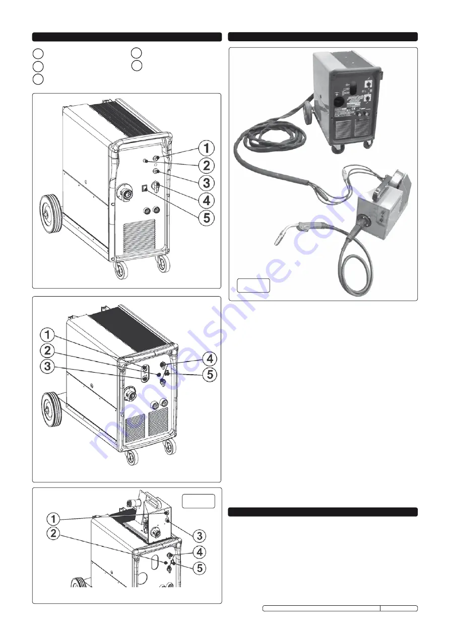
USING REMOTE WIRE DRIVE Models 3500 & 4500.
The wire drive unit supplied with the models 3500 & 4500 is a
separate entity which can be mounted inside the welder (as supplied),
on top of the welder (as shown in fig.23), or remotely from the welder
by the connection of an umbilical lead assembly as shown in fig.24 .
7.1.1
Lift the side panel to access the drive unit.
7.1.2
Unplug the circular dinse connector and the adjacent square
connector to be found in the left hand side of the compartment.(fig.22)
7.1.3
Undo the butterfly bolt that secures the unit.
7.1.4
The unit may be placed on top of the welder where a location hole
is to be found, and secured with the butterfly bolt.
7.1.5
Pass the connectors through the hole in the rear bulkhead adjacent to
the internal sockets and re-connect the dinse and square connectors,
and fit the torch to the euro-connection on the portable unit.
The wire drive may also be used away from the welder with optional
umbilical extensions.
Contact your local Sealey dealer to order:
3 metre umbilical lead assembly model no. 120/802271.
9 metre umbilical lead assembly model no. 120/802272.
7.2
SYSTEM PROTECTION
To provide a level of protection against faults such as short circuits or
overheating, two safety features are incorporated in the welder unit.
The auxiliary circuit is protected by a 1 Amp fuse located on the
auxiliary transformer. Two thermostats are built into the system to
protect against overheating, the second providing a margin of safety
should the first thermostat fail. Regularly check the thermostats to
ensure they are correctly in contact with adjacent parts.
The indicator light comes on when there is overheating and cuts off
the power supply; it will reset automatically within a few minutes, after
cooling down.
IMPORTANT.
Should you have no welding experience, we recommend you seek
training from an expert source to ensure your personal health & safety.
You must familiarise yourself with welding applications and limitations,
and specific potential hazards peculiar to welding. Good Mig welding
may be achieved only with continued, supervised practice.
8.1
MIG/MAG welding.
(See fig.25 ). A spool of welding wire is placed on
the spool holder and automatically fed through an insulated liner in the
torch to its tip. The torch consist of a switch, liner, gas hose, and
control cable. The switch activates the wire feed roller and the gas
flow. Releasing the switch stops wire feed and gas flow. The weld
current is transferred to the electrode (the wire) from the contact tip at
the torch end.
8. WELDING PRINCIPLES
6. POWERMIG CONTROLS
7 . REMOTE WIRE DRIVE UNIT
POWERMIGS 3500 & 4500
REMOTE WIRE DRIVE FOR MODELS 3500 & 4500
POWERMIG 2750
1 WIRE FEED RATE
2 ThERMOSTAT TRIGGER LIGhT
3 WELDING TIME
4 ARC VOLTAGE ADJUSTMENT
5 MAIN SWITCh
fig.23
fig.24
Original Language Version
POWERMIG2750.V2, POWERMIG3500.V2, POWERMIG4500.V2 Issue: 3 - 09/04/10


