3. ASSEMBLY & INSTALLATION
Carefully remove outer carton and packing. Be very careful when removing the
welding unit from the packing base as the unit is very heavy, we recommend
that unpacking the base and wheel assembly is undertaken by two persons.
Check the welder and contents. Should there be any damaged or missing parts
contact your supplier immediately.
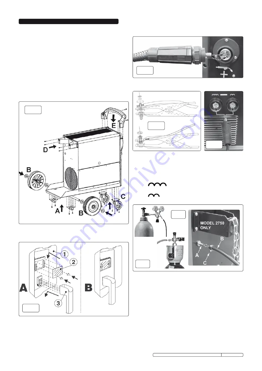
3.1. WELDER ASSEMBLY (fig.3).
3.1.1 WHEELS - Attach the axle to the underside of the bottom tray using the
two top hat sections provided. (See fig.3A) Do not fully tighten until the
wheels are attached. Slide a washer over each end of the axle followed
by a wheel followed by another washer. (See fig.3B) Retain the wheels
by inserting a spilt pin through either end of the axle. Check that the
wheels can rotate freely then tighten the top hat sections. Attach the
front castors to the unit using the self tapping screws provided as
shown in fig.3C.
3.1.2 GAS BOTTLE REST - Attach the gas bottle rest to the rear face of the
welder using the self tapping screws provided as shown in fig.3D.
3.1.3 Push the handle down into the recesses provided at the top of the front
face of the welder as shown in fig.3E. Retain the handle on either
side using the self tapping screws provided.
fig.3
fig.8
3.3
CONNECTION TO ThE MAINS POWER SUPPLY.
3.3.1 Before making any electrical connections, ensure that the mains voltage
and frequency of the supply matches the electrical specification of the
welder as stated on the welder’s rating plate.
3.3.2 The welder must only be connected to a three phase power supply with
the neutral conductor connected to earth.
3.3.3 Refer to the section on electrical safety at the start of these instructions
for information on the correct connection of the mains power plug.
3.2
WELDING MASK ASSEMBLY (fig.4).
3.2.1 Assemble the welding mask as shown below.
3.5
EARTh CLAMP (fig.6).
3.5.1 Assemble the earth lead to the earth clamp as shown below left.
3.7 Connecting the gas cylinder (fig.8 & 9).
3.7.1 Stand the gas cylinder on the platform at the rear of the welder and
secure with chain supplied.The platform is designed to support bottles
up to a maximum weight of 20kg.
3.7.2 If using Argon or Argon mixtures, you will need to use the “bull nose
adaptor” enclosed. If you intend to use CO2 gas the regulator will fit
directly onto the cylinder. If using the bull nose, fit nose adaptor to the
cylinder and tighten with a spanner.
3.7.3 Remove regulator from box and screw it to the bull nose adaptor (or
CO2 cylinder). Slide a small jubilee clip over the rubber hose from the
welder , connect the hose to the regulator “BP” output and secure with
the jubilee clip (fig 8). On model 2750 connect the gas hose to the gas
inlet on the rear of the welder (See fig.9A). Tighten the jubilee clip.
3.7.4 Close the regulator by turning the adjusting screw anti-clockwise to
relieve the pressure on the diaphragm before opening the cylinder
valve. If this is not done, pressure from the cylinder can damage the
diaphragm and render the regulator inoperative.
3.7.5 Set the regulator flow rate to 4litres/min depending on the material to be
welded, also taking into consideration any draughts which are strong
enough to disturb the gas flow.
3.6
Connecting the welding current return cable (fig.7).
The earthing clamp should be firmly attached to the piece being
welded ( or to a metal bench supporting it ), as close as possible to
the joint being made. The quick connector at the other end of the
cable will be connected to one of the terminals identified with a
minus symbol ( - ). There are two alternative connections offering
different reactance levels depending on the type of material being
welded.
The lefthand socket as shown above has maximum
reactance and is intended for aluminium material and derivative
alloys (Al), copper alloys (CuAl/CuSi).
The right hand socket has minmum reactance and is
intended for stainless steel (SS), carbon steel and low alloys (Fe).
3.4. TORCh “Euro Connection” (fig.5).
Your welder is fitted with a “Euro Connection” quick release torch.
Simply line the pins in the torch up with appropriate holes on the front
panel connector and push in and tighten the locking nut.
fig.4
fig.5
fig.6
fig.7
fig.9
Original Language Version
POWERMIG2750.V2, POWERMIG3500.V2, POWERMIG4500.V2 Issue: 3 - 09/04/10


