background image


DOCS-004 Manual, LBV300-6 and LBV600-6 Rev C – 12APR10 Page 7 of 8 


Please refer to your LBV configuration to determine which channels are 
utilized on your LBV. 


3.2 No Link  


If you receive no link indications, the issue is possibly in the tether itself.  To test, 
disconnect the fiber from the LBV, remove the Pull Out Hub from the reel, and 
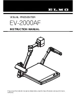
disconnect the fiber optic cable.  Use a high intensity white light, LED flashlight or 
similar, to shine light from end to end. 
 
NOTE:  The fiber optic connector must be centered over the light source for this test to 
work. 


Light shining into the wet end (FC) connector 
of the tether. 

Light shining,  
Fiber OK 

No Light  
Bad Fiber 

 
If there is no light transmission, the fiber optic cable inside the tether is damaged.  At 
this point, you will need to get access to a fiber optic TDR (Time Delay Reflectometer) 
to determine at what point in the tether the damage has occurred.  SeaBotix Inc. does 
offer a Fiber Optic Re-termination Kit to allow the user to complete this repair in the 
field.  Please contact 

[email protected]

 to assist in identifying the proper kit for 

your application. 
 
A ST-ST fiber optic cable can be utilized to verify that the issue is in the tether itself.  To 
perform this verification, insert one end of the ST fiber cable into the FC connector on 
the rear of the LBV and install the other end onto the connector on the MUX hub.  Leave 
the wet mateable connector and the silver ODU connector for POWER connected.  Turn 
the LBV on. If the LBV operates correctly at this point, the issue is a faulty fiber in the 
tether itself. 

Содержание DOCS-004

Страница 1: ...9437 5400 2009 by SeaBotix Inc All Rights Reserved ADDENDUM USER MANUAL LBV300S 6 LBV300XL LBV600XL DOCS 004 Rev C The information photographs illustrations and descriptions contained in this manual are the property of SeaBotix Inc Unauthorized duplication and distribution is strictly forbidden Additionally SeaBotix Inc reserves the right to alter any and all information contained in this manual ...

Страница 2: ...r 09 Contents Section 1 The LBV 1 Section 2 Bumper Frame and Float Removal 3 Section 3 Care and Troubleshooting of the Fiber Optic Cable 4 3 1 Data Communications error and or loss of video 5 3 2 No Link 7 Section 4 URS350 or URS750 REEL 8 ...

Страница 3: ...on 1 The LBV The LBV should always be handled by the bumper frame only Utilize the cutouts as shown below to handle the LBV Do not utilize the thruster guards the thrusters or any other attached devices as they are not designed to handle the weight of the LBV in the air ALWAYS LIFT THE LBV BY THE HANDLE HOLES PROVIDED 1 1 The LBV300XL and LBV600XL have been equipped with a 1200 watt Vehicle Power ...

Страница 4: ...that of the LBV150 The communications and video transfer takes place via a fiber optic line inside the tether 1 3 To trim the weight on the LBV use the lead strip mounting locations as shown above blue arrows 1 4 Always trim your LBV for the water in which you will be flying it Proper trim facilitates LBV control and extends thruster life ...

Страница 5: ...BV Lay each bumper frame to the side 2 5 Use the service manual instructions for removing a body float to remove the LBV float 2 6 Remove the cables from the aux 1 and aux 2 connections on the backplane This procedure now frees the bumper frames from the LBV Assembly and disassembly instructions are identical to the instructions on the SeaBotix Inc web site for assembly and disassembly of the LBV1...

Страница 6: ...an 150mm 6 dia on the fiber optic lines or the tether 3 0 2 When operation of the LBV is complete rinse both the fiber and power connectors with fresh water 3 0 3 Always dry the end of the fiber connector before installing the protective boot cap 3 0 4 Always ensure that the fiber bulkhead connector on the LBV is dry prior to connecting the tethers fiber connector 3 0 5 Do not use sharp objects to...

Страница 7: ...ey is not aligned correctly 2 Water in the bulkhead connector 3 Foreign object or debris in the bulkhead 3 1 Data Communications error and or loss of video The image on the next page is the Local Fiber Optic Board PCA039 mounted in the Pull Out Hub of the Universal Reel System By component layout it is identical to the board mounted in the camera chassis of the LBV The part number for the LBV boar...

Страница 8: ...ta Transmission Blinking RED indicates NORMAL state Data Transmitting Channel 2 RS 485 TX OUT GREEN Solid GREEN indicates HIGH state No Data Transmission LED OFF indicates LOW state but No Data Transmission Blinking GREEN indicates NORMAL state Data Transmitting 6 Channel 3 RS 232 RX IN RED LBV Control Solid RED indicates HIGH state No Data Transmission Check RS 232 GND Pin 1 connection LED OFF in...

Страница 9: ...mission the fiber optic cable inside the tether is damaged At this point you will need to get access to a fiber optic TDR Time Delay Reflectometer to determine at what point in the tether the damage has occurred SeaBotix Inc does offer a Fiber Optic Re termination Kit to allow the user to complete this repair in the field Please contact service seabotix com to assist in identifying the proper kit ...

Страница 10: ...t back from the reel Use this same procedure to remove the handle from the handle holder 4 3 Avoid lifting the reel by the chrome bars ALWAYS USE AT LEAST TWO PEOPLE TO LIFT THE REEL ALWAYS SECURE THE REEL TO THE DECK OR THE DOCK UNDER HIGH LOAD CONDITIONS MONITOR THE TEMPERATURE OF THE TETHER ON THE REEL IF IT STARTS GETTING WARM POUR COOL WATER OVER THE TETHER EVERY FEW MINUTES If you have any q...

Отзывы: