background image

7

20.7”

13.6”

12.8”

V  (±5%) 50/60 Hz

      120
        24V                   24V
      130 W                160W
     2,45 A                   3,5 A
     0/35 Nm             0/40Nm
              adjustable
                    40%                     
     662 Lb                 880 Lb
                    40 ft
          electromechanical
         from -4°F to 131°F
                   73 Lb
                   IP 55
             I    II    III    IV

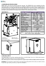
1. FEATURES AND SPECIFICATIONS

ORION BOX is an electro-mechanical reduction operator. The ORION BOX can be supplied with either 
mechanical clutch or electronic sensing device as methods of limiting the motor torque. The gates open & 
close stop limits are accurately stored by mechanically triggering the on-board micro-switch. Manual release 
is quickly achieved by operating a key manual release system.The control unit allows to choose between 
automatic or semi-automatic control logic and will provide all normal safety logic functions

TECHNICAL FEATURES
Power supply
Motor power supply
Power
Absorbed current
Thrust force
Leaf speed (pinion Z20)
Use rate
Max gate weight
Max gate opening
Type of limit switch
Operating temperatures
Operator weight
Protection class
Classification

ORION BOX 24V ORION BOX 24V FAST

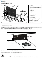
1

 Release 

2

 Limit switch

3

 Foundation plate

4

 Control unit

5

 General switch

1

2

3

4

5

NOTE: The frequency of use is valid only for the first 

hour  at  68° F  room  temperature

2. GENERAL SWITCH

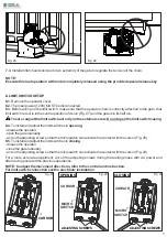
Into ORION BOX you can find a general switch (Fig. 13) which allows to turn on or off the electric power 
supply. This switch must be set on «

I

» to start the operator

CAUTION:


Operator


must


be


started


only


after


having


correctly


installed


and


adjusted


all components

WARNING! 

It is mandatory to switch off the power supply by putting switch to «

O

» when you need to work on 

the operator (eg. repairs, power loss, components installation).

COMPONENTS

DIMENSIONS

5

Fig. 12

Fig. 13

Fig. 14

Содержание ORION BOX 24V

Страница 1: ...ORION BOX 24V REV 03 09 2020 SEA USA Inc 10850 N W 21st unit 160 DORAL MIAMI Florida FL 33172 Phone 1 305 594 1151 Toll Free 800 689 4716 www sea usa com 67411520...

Страница 2: ...ildren to play or stay within the path of the moving gate 9 Keep remote control or any other control devices out of the reach of children in order to avoid possible involuntary activation of the gate...

Страница 3: ...tor Instructions regarding intended installation of the gate operator shall be supplied as part of the installation instructions or as a separate document The following instructions or the equivalent...

Страница 4: ...ll provide warning notices on not assessable further risks SEA USA Inc in its relentless aim to improve the products is allowed to make whatsoever adjustment without giving notice This doesn t oblige...

Страница 5: ...objact closer than 16 inches 406mm are not required to be provided with a means of entrapment protection B1 and B2 means of entrapment protection MUST be MONITORED HORIZONTAL SLIDE VERTICAL LIFT VERT...

Страница 6: ...ent fig 11 GATEARRANGEMENT The first thing to check is that the gate is in good running order as follows a The gate is rigid and straight and runs smoothly throughout its travel b That the inferior sl...

Страница 7: ...ICAL FEATURES Power supply Motor power supply Power Absorbed current Thrust force Leaf speed pinion Z20 Use rate Max gate weight Max gate opening Type of limit switch Operating temperatures Operator w...

Страница 8: ...the gate from derailment Fig 16 4 TYPE OF INSTALLATION 3 TYPICAL INSTALLATION 1 Operator 2 Concrete to build operator on 3 Photocells 4 Safety edge 5 Key switch 6 Travel gate stops 7 Radio receiver 8...

Страница 9: ...d in that portion of the adjacent fence that the gate covers in open position 5 5 Follow the local building code to determine the required depth of the concrete pad 5 6 SEArecommend the following pad...

Страница 10: ...ain with the provided tie rod Fig 22 Fig 22 Fig 23 7 2 Install the chain making it pass through the pinion group as in Fig 24 The chain must be always in line both vertically and orizontally if not pe...

Страница 11: ...nal screw the limit switch casing 8 4 To install and adjust the limit switches in opening release the operator open the gate manually act on the adjusting screw so that the microswitch can activate th...

Страница 12: ...ower 120V before servicing the operator RELEASE Fig 30 Fig 31 Fig 32 Fig 33 SEA recommend to release the operator only in case of power failure Always contact a pro fessional installer in case of malf...

Страница 13: ...TING Fig 34 Fig 37 Fig 38 Fig 39 Fig 36 Fig 35 Note The antenna must be connected on the clamps 1 and 2 of the control unit CN1 connector For further information on the antenna wiring diagram please r...

Страница 14: ...arantee will be void and the manufacturer responsability will be nullified if SEAUSAInc original spare parts are not being used The electrical installation shall be carried out by a professional techn...

Страница 15: ...l be refused Customers must contact SEAfor instructions WARRANTY for the original buyer only Hydraulic and oil bath motors 36 months warranty from the date of invoice on manufacturing assembling and w...

Страница 16: ...SEA USA Inc 10850 N W 21st unit 160 DORAL MIAMI Florida FL 33172 Phone 1 305 594 1151 Toll Free 800 689 4716 www sea usa com sales sea usa com...

Отзывы: