Installation
6012-12W Installation Manual
3.8.1.
Connecting the BDE AC Power Cables
Connect the AC Power cables that supply power to the Below Decks Equipment (MXP, BDE
Fiber Enclosure, TXRX Dual Antenna Arbitrator, Satellite Modem, phone, fax, computer and all
other equipment) to an outlet strip fed from a suitably rated breaker or UPS.
3.8.2.
Connecting the ADE-BDE Coax Cables
Connect the TXIF Cable to the TX connector on the ADE-BDE coax interconnect bracket.
Connect the TXIF Cable to the TX connector on the ADE-BDE coax interconnect bracket.
3.8.3.
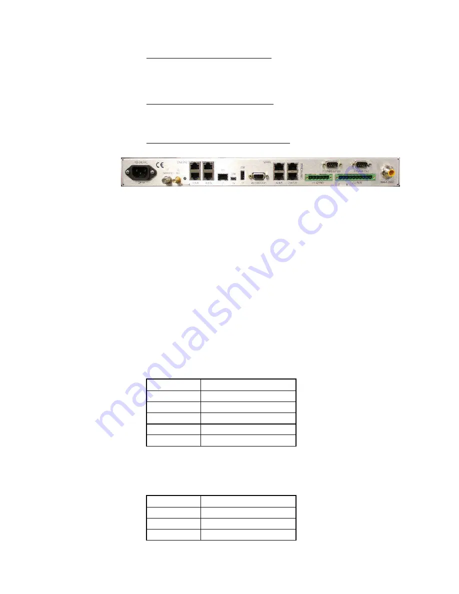
Media Xchange Point™ (MXP) Connections
Ships AC Mains -
Connect the power cord from the rear panel of the MXP to AC voltage power
source (UPS power recommended).
J1 Modem -
Previously connected to the RX INPUT connector on the rear panel of the Timing Rack.
J2 RJ -
Previously connected to the J4 RXIF Output (to ICU) connector on the rear panel of the Dual
Modem Arbitrator.
J3 A/B & J4 A/B - Ethernet 4 Port 10/100 switch -
Ethernet connections to computer, satellite
modem LAN devices as desired. Connect a CAT5 cable from J3A to an open RJ-45 connection on the
CFE Router.
J5 SFP Fiber Interface -
SFP Gigabit Ethernet connection.
J6 Mini-USB Computer M&C Connection -
Mini-USB Antenna M&C connection, if desired.
J7 USB Host - Not connected - -Future development
.
J8 Console -
Antenna M&C Serial connections.
J9 A/B Serial -
Computer RJ-45 Serial M&C connections. A is mapped to the Radio serial M&C port
of the ICU and B is mapped to the Pass through serial M&C port of the ICU.
J10C Modem -
RJ-45 Serial M&C connection to DAC A Input on the TX/RX Dual Antenna Arbitrator.
J10D OBM -
RJ-45 Serial M&C connection to Out of Band Management equipment, if used.
J11 Gyro -
Terminal Strip for SBS or Synchro Gyro Compass interface connections. Wiring is:
Pin 1
Synchro R1
Pin 2
Synchro R2
Pin 3
Synchro S3 / SBS A
Pin 4
Synchro S2 / SBS B
Pin 5
Synchro S1 / SBS C
Pin 6
SBS COM
J13 NMEA 0183 -
NMEA 0183 I/O connections. J11 NMEA port on the rear panel is used for NMEA
0183 Gyro Compass input to the MXP. The +12 VDC output is only intended to power a very low
current consumption device, do NOT exceed
125ma MAX.
Wiring is:
Pin 1
RX+ NMEA
Pin 2
RX- NMEA
Pin 3
TX- NMEA
Pin 4
N/C
3-9
EAR Controlled - ECCN EAR99
Содержание 6012-12w
Страница 33: ...Installation 6012 12W Installation Manual This Page Intentionally Left Blank 3 13 EAR Controlled ECCN EAR99 ...
Страница 59: ...6012 12W Installation Manual Setup Targeting This Page Intentionally Left Blank 9 4 EAR Controlled ECCN EAR99 ...
Страница 94: ...6012 12W Installation Manual DRAWINGS This Page Intentionally Left Blank 15 2 EAR Controlled ECCN EAR99 ...
Страница 101: ......
Страница 102: ......
Страница 103: ......
Страница 106: ...8 7 6 5 4 D 5 C B A 8 7 6 5 4 ...
Страница 116: ...8 7 6 5 4 3 50 58 58 59 2X 1 52 58 58 59 2X ...
Страница 120: ......
Страница 128: ......
Страница 129: ......
Страница 130: ......


