6012-12W Installation Manual
Installation
3.4.
Grounding the Pedestal
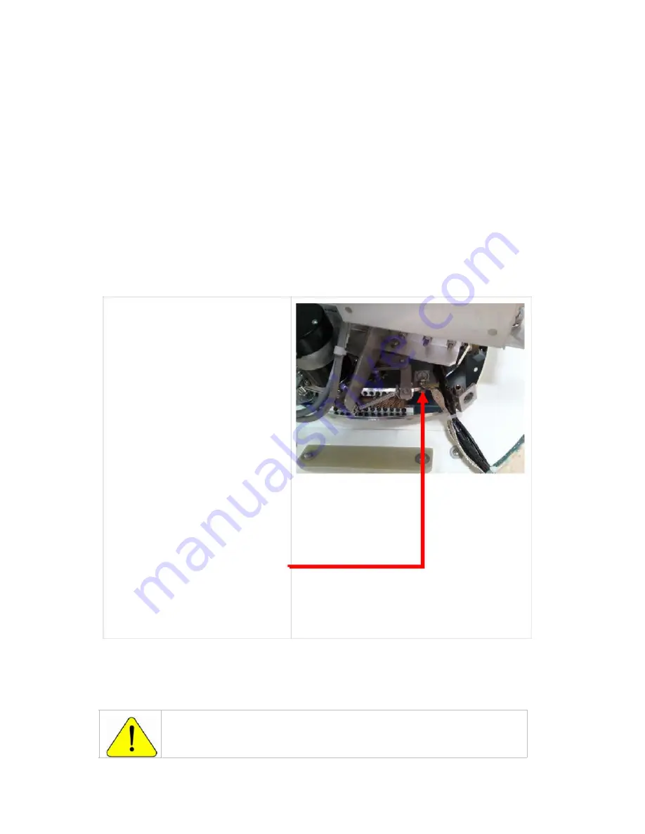
The antenna pedestal must be grounded to the hull of the ship. A grounding point is provided on the upper
base plate to ground the pedestal. A ground wire, of appropriate gauge for it’s length, must be provided to
ground the pedestal to the mounting platform that it will be bolted to (this is usually on or near the
mounting surface). This mounting must also be electrically common with the hull of the vessel.
If a longer ground connection is required to reach a common metal connection to the hull, you must provide
that longer cable/strap that is of sufficient gauge and length to ground the pedestal to the nearest grounding
point of the hull.
Solid strap
is the conductor of choice for low impedance RF ground connections because the RF currents
tend
to flow along the outer surface and the strap has a large smooth surface area to take full advantage of
this effect.
Braid
is the conductor of choice where flexibility is required. Sea Tel uses braid to cross axes of the antenna
pedestal and to connect various subassemblies together.
Wire
is the easiest to install and connect and is readily available with a weather protective jacket. 4 awg and 6
awg bare solid copper wire is commonly used as safety grounds and very basic lightning protection grounds.
2 awg stranded wire is often used for lightning grounding and bonding and it much more flexible.
1.
Connect the ground wire (of
adequate gauge for the length) to
a burnished ground point on, or
near, the mounting surface. This
burnished grounding point must
be electrically common with the
hull. Bi-metal coupling plate may
be required to get good electrical
coupling to the hull of the ship.
Protective coating should be
applied to prevent the grounding
point, and ground wire, from
rusting or corroding.
NOTE: Minimum
gauge should not be
smaller than
10 AWG
, even for a short
cable run.
2.
Route the ground cable/strap up
through the radome base with
the coax and power cables.
3.
Route the ground strap/cable
through one of the Roxtec®
Multidiameter® blocks with the
other power and coax cables.
4.
Connect the grounding
strap/cable to the burnished
ground point on the upper
base plate.
3.5.
Removing the Shipping/Stow Restraints PRIOR to Power-Up
The order the restraints are removed is not critical.
CAUTION:
There are three shipping/stow restraints on this antenna pedestal
that
MUST
be removed,
before energizing
the antenna, for normal operation.
3-4
EAR Controlled - ECCN EAR99
Содержание 6012-12w
Страница 33: ...Installation 6012 12W Installation Manual This Page Intentionally Left Blank 3 13 EAR Controlled ECCN EAR99 ...
Страница 59: ...6012 12W Installation Manual Setup Targeting This Page Intentionally Left Blank 9 4 EAR Controlled ECCN EAR99 ...
Страница 94: ...6012 12W Installation Manual DRAWINGS This Page Intentionally Left Blank 15 2 EAR Controlled ECCN EAR99 ...
Страница 101: ......
Страница 102: ......
Страница 103: ......
Страница 106: ...8 7 6 5 4 D 5 C B A 8 7 6 5 4 ...
Страница 116: ...8 7 6 5 4 3 50 58 58 59 2X 1 52 58 58 59 2X ...
Страница 120: ......
Страница 128: ......
Страница 129: ......
Страница 130: ......


