background image

CME1856W

November 2001

Page 7

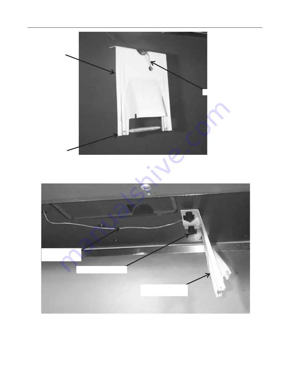
Bin Control

Attach Thermostat Bulb to Bracket

Bin Thermostat

Bracket

Attach Bracket to Bottom of Ice Machine

Minimize Excess

Tube in Bin

Bin Thermostat Capillary Tube

Three-Pronged Knob

Thermostat and

Bracket

Mount Bulb Here

Содержание CME1856W

Страница 1: ...6 LG B PAGE 11 Stacking PAGE 12 After Utility Connections PAGE 13 Component Location and Function PAGE 14 System Controller PAGE 15 Initial Start Up PAGE 16 Adjustments PAGE 17 How To Operate The Controller PAGE 18 How The Electronic Cuber Works PAGE 19 How The Electronic Cuber Works PAGE 20 Startup Three Phase Compressor PAGE 21 Technicians Only Freeze Cycle Sequence PAGE 22 Technicians Only Harv...

Страница 2: ... including the use of any parts and or other components not specifically approved by Scotsman Bins All models will fit a standard 48 wide or wider open top Scotsman Ice Storage Bin Some examples are BH900 BH1370 BH1356 BH1650 BH1000 requires kit KBT21 In addition there may be other bins that can be used check Scotsman s sales literature for application information Note Slope front bins must have a...

Страница 3: ...CME1856W November 2001 Page 3 Ice Machine Layouts ...

Страница 4: ... what ends up in the bin as ice While most water is used during ice making a portion is designed to rinse out the water system to keep hard water scale from clogging up the machine That water rinse combined with water filters prolongs the times between needed water system cleaning Service Technicians All models covered here come set from the factory with at a Standard water rinse Standard water ri...

Страница 5: ...k and left to right If the ice machine has not been unpacked do so now Remove the carton from the skid Remove shipping straps Remove the front and left panels Remove the compressor shipping brackets and all packaging materials After all packing materials have been removed from the ice machine lift or hoist the machine onto the bin Align the sides and back of the machine with the sides and back of ...

Страница 6: ...to the bottom of the ice machine with the two 3 pronged knobs supplied with the unit 6 Pull back into the ice machine any excess capillary tubing 7 Return the baffle to the bin and continue with the installation Note If the machine is located at an altitude higher than 2 000 ft adjust the thermostat by removing the plastic cover and rotating the adjustment screw per the table Route Bin Thermostat ...

Страница 7: ...e 7 Bin Control Attach Thermostat Bulb to Bracket Bin Thermostat Bracket Attach Bracket to Bottom of Ice Machine Minimize Excess Tube in Bin Bin Thermostat Capillary Tube Three Pronged Knob Thermostat and Bracket Mount Bulb Here ...

Страница 8: ...ing tower requires the heat of rejection and the pressure drop across the ice machine s water cooling circuit water regulating valve and condenser Heat of Rejection 27 400 BTUH Peak Pressure Drop 7 psi Maximum water temp into condenser 110o F Peak GPM at 110o F 9 10 GPH at 110 100 372 GPH at 90 70 107 GPH at 70 50 59 CME1856W October 2001 Page 8 ...

Страница 9: ...ividually fused Voltage variation must not exceed the limits listed on page 2 Electrical connections are made in the junction box in the back of the cabinet 1 Remove the junction box cover 2 Knock out one hole for a field supplied strain relief 3 Install wires and strain relief per code 4 Connect to wires and secure ground wire to ground screw inside junction box All external wiring should conform...

Страница 10: ...ill cause severe operational issues Check with the filter manufacturer When replacing a prior ice machine do NOT assume that the water flow capacity of the filter will be adequate Filtering the condenser water supply is not recommended All Drain Tubing Material must be RIGID Flexible tubing will eventually kink and cause a restricted drain Drain Connect a 3 4 drain tube to the reservoir drain fitt...

Страница 11: ... front to back support bracket over the left edge of the freezing compartment 11 Remove two existing screws and secure the bracket to the freezing compartment back panel and front channel with the 2 existing screws and 1 large and 4 small screws from the kit Both Machines 12 Place the top ice machine onto the bottom one Secure together with hardware from the top machine Remove left front and left ...

Страница 12: ...ME1856W November 2001 Page 12 Stacking Gasket for Metal Edges of Bottom Unit Gasket on Plastic Walls of Lower Unit Shield Hanger Bracket Mounting Straps and Hardware Front to Back Support Bracket Shield ...

Страница 13: ...y made with the correct size tubing ___ 5 Have all the drain connections been properly made ___ 6 Has the unit been leveled Level the unit at the bin ___ 7 Have all unpacking materials been removed ___ 8 Is the water pressure adequate ___ 9 Is the machine secured to the ice storage bin ___ 10 Is the bin control system been properly installed ___ 11 Have the drain connections been checked for leaks...

Страница 14: ...the bin Water Pump Forces the water from the reservoir to the top of the evaporators The motor is kept separate from the water to minimize contact with moisture Hot Gas Valve Closed during freeze it opens during harvest to divert hot discharge refrigerant gas into the inlet of the evaporators Purge Valve Opens during the first part of harvest when the water pump restarts the water in the reservoir...

Страница 15: ...e evaporators The compressor and water pump are ON Harvest The refrigeration and water systems are operating to harvest the ice cubes While the compressor is on for the full cycle the water pump will be off at the beginning and the inlet water valve will switch off before the end Clean Water valve opens to fill the reservoir The Water pump starts The Clean indicator light is switched ON A manually...

Страница 16: ...eeze cycle The freeze cycle will continue until the water level in the reservoir drops to its factory set point the first time that happens the water valve will re fill the reservoir The second time it starts the Harvest Cycle Harvest Cycle The Harvest indicator light will be ON The hot gas valve will open The purge valve will be open for 74 seconds The pump is off it will restart in 74 seconds Th...

Страница 17: ...his switches the machine Off 2 Push and hold the OFF button for more than 3 seconds just until all Lights flash on then release it Do not hold it in it too long 3 Examine the green Lights They should have all flashed once then certain ones will have turned on to indicate which purge level the machine is set at There are 5 levels of purge available 1 Maximum Purge is when All 5 lights are ON Use fo...

Страница 18: ...n Button Pushing and releasing this button will cause the machine to empty the reservoir refill and leave only the water pump on for circulation of ice machine cleaner After the ice machine cleaner has circulated for about 10 minutes a second push of this button will switch on the rinsing system to flush out the dissolved scale and ice machine cleaner 4 Off Button Pushing and releasing this button...

Страница 19: ... evaporators and ice will form at the top first When cubes need to be released Harvest the Hot Gas Valve is opened and Hot discharge gas flows directly from the compressor to the evaporator inlets This warms up the evaporators and the surface of the ice frozen to the evaporator surface melts Ice then falls into the bin CME1856W November 2001 Page 19 Evaporator Evaporator Evaporator Compressor Wate...

Страница 20: ... the ice machine by monitoring several input measures and switching various loads on and off Controller Inputs 1 Reservoir water temperature This is measured by a thermistor located in the water pump outlet 2 Discharge line temperature This is measured by a thermistor located on the compressor discharge line 3 Water level This is measured by an infrared sensor and float The float rises and falls w...

Страница 21: ...he ice machine does not appear to be refrigerating the water it s likely that it s running backwards To fix this two of the three compressor motor leads need to be reversed 1 Disconnect electrical power 2 Remove left front panel 3 Pull off compressor terminal cover 4 Locate terminals switch any two wires 5 Return compressor terminal cover to its original position 6 Reconnect electrical power 7 Pus...

Страница 22: ...e Controller then measures how long it takes to lower the water level If the water level does not fall the machine Shuts Down on a Water Error 7 Once per freeze cycle the machine will shut off the water pump It only does this when the water temperature reaches a preset minimum The pump will only be off for a few seconds 8 As the machine makes ice the water level in the reservoir will ultimately fa...

Страница 23: ...ply to a single phase unit is interrupted for less than a second a time delay relay will keep the compressor from restarting until 30 seconds have passed Because the controller should still be operating Continuous Run Time A unit that operates 24 hours a day 7 days a week is too small for the user s needs To maintain harvest integrity the controller will extend the harvest time to 6 minutes every ...

Страница 24: ... 9 After the ice machine cleaner has circulated for 10 minutes push and release the Clean button This starts the rinsing process The Clean indicator light will be ON Note The rinse process flushes any residual cleaner out of the ice machine s water system 10 Continue the rinsing process for 20 minutes then push the off button to switch the machine off 11 Go to the next step to sanitize the machine...

Страница 25: ...chine shuts off 3 Push and hold the Clean button for 3 seconds The water pump will discharge water out the open purge valve 4 When the reservoir is empty release the Clean button and push and release the Off button 5 Push and release Freeze button to restart 6 Return the front panel to its original position To Sanitize the Ice Storage Bin 1 Remove all ice 2 Remove baffle 3 Switch ice machine OFF o...

Страница 26: ...tors The Water Distribution Channels must be free from mineral build up If build up is evident scrub the channels with Scotsman Ice Machine Cleaner and a plastic bristle brush 9 Examine the water distributors Although they are made of a material that is resistant to mineral build up some may be present Soak or scrub the distributors in or with a solution of Scotsman Ice Machine Cleaner and warm po...

Страница 27: ...ff screen Note Screen is not replaceable and may only be removed by taking off the covering bracket The bracket forms part of the inlet water system and must be water tight to the valve body removal is not recommended 9 Reverse to reassemble Water Level Sensor The water level sensor contains two photo electric eyes and each eye has an emitter and a receiver For proper operation the receiver must b...

Страница 28: ...pots 8 Reverse steps 1 6 to reassemble To Clean the Water Cooled Condenser Under typical water conditions the condenser will not require any maintenance However if the water supply contains a large amount of minerals the water cooled condenser may become coated internally with scale The symptom of a dirty water cooled condenser is abnormally high water use Do NOT perform this procedure too frequen...

Страница 29: ...ill not reset or gives another water error and all else is OK replace the water level sensor Unit is off and the Refrigeration Diagnostic Light is ON or BLINKING Low discharge or long freeze cycle Check refrigeration Light If the Light is glowing there is a probable refrigeration problem Check water supply and or water regulating valve Harvest problem Check refrigeration Light If the Light blinks ...

Страница 30: ... Check clean water sensor eyes Check for a leak thru the purge valve Low ice capacity Water regulating valve pressure adjusted too high Adjust water regulating valve to 240 PSIG of discharge pressure in freeze Low refrigerant charge Check system If there is a low charge find the leak recover the refrigerant repair the leak replace the dryer evacuate and weigh in the nameplate charge Too much water...

Страница 31: ...anical problem in valve Replace valve Water Inlet Valve does not open Open solenoid coil Replace valve Stuck valve Replace valve No power to valve best checked at the beginning of Freeze Check wire connections if ok replace Controller Water Inlet Valve does not flow enough water Restriction in water supply Check water filters and or inlet screen Water Inlet Valve leaks thru Mechanical problem in v...

Страница 32: ...gulating valve Low Capacity Extreme hot location Relocate the cabinet Overcharge of refrigerant Recover evacuate and weigh in the nameplate charge Hot gas valve leaks thru unit off on refrigeration error At the end of the freeze cycle there should be a definite difference in temperature between the inlet and outlet of the Hot Gas Valve If not replace the hot gas valve Compressor cycles on and off ...

Страница 33: ... Discharge Minimum in Harvest 140 PSIG 140 PSIG 0 2 4 6 8 10 12 14 Beg 2 mins 3 mins 5 mins 1st fill 10 mins End Hvst End Hvst Three Phase Amp Draw Freeze Cycle Harvest Number of Evaporators 6 Refrigerant Charge 60 ounces of R 404A Compressor Type Three Phase Copeland Scroll ZS30K4E TF5 230 Single Phase Copeland Scroll ZS30K4E PFV 230 Typical Compressor Amps single phase freeze 19 6 harvest 22 5 t...

Страница 34: ...CME1856W November 2001 Page 34 Suction Pressure Suction Prssure 0 10 20 30 40 50 60 70 80 90 Time PSIG Pressures During Freeze and Harvest at 70o F Air and 50o F Water ...

Страница 35: ...the replacement part 1 Touch a grounded surface 2 Remove left front panel 3 Disconnect electrical power 4 Remove high voltage box cover 5 Locate timer board at the back of the high voltage box 6 Unplug all the wires to the board 7 Compress each of the four stand off posts to release the board from the stand offs 8 Remove the board from the unit Reverse to reassemble Water Pump 1 Disconnect the ele...

Страница 36: ...t one 1 Disconnect the electrical power 2 Remove the front panel 3 Remove 1 plastic bolt and the reservoir cover 4 Pull float ball from float stem it is a snap fit Pull stem out 5 Locate water level sensor mounting tabs compress together to release sensor from bracket 6 Remove harness from sensor 7 Reverse to replace 8 Replace front panel 9 Re connect electrical power Water Level Sensor 1 Remove f...

Страница 37: ...thing for 60 seconds or push and release the Off button After returning from the display of the last error Off light glows the machine may be returned to the ice making process by pushing and releasing the Freeze button Program ID The blue housing controller will display a code at power up that indicates which ice machine model it has been programmed for The code is based on the green lights that ...

Страница 38: ...ectric Eyes Ice Sensors These must be replaced as a set 1 Remove both front panels 2 Push and release the Off button 3 Remove evaporator cover 4 Remove lower inner splash panel 5 Locate the back electric eye Pull out on the rectangular tab until the sensor is free of its installed position 6 Unplug the back sensor from its wire harness 7 Unplug the front sensor its wire harness 8 Locate retainer c...

Страница 39: ...it will not start check the starting components first If the machine has low capacity check for proper charge TXV operation hot gas valve leak thru or inlet water valve leak thru The metal bracket in front of the compressor must be removed to access the compressor Note This machine uses a Copeland Glacier scroll compressor which has the following unique operating characteristics 1 Do NOT bypass th...

Страница 40: ... the right side of the freezing compartment Then while the helper lifts the right most evaporator slightly push the bracket in from below Keep doing this and push up on the left end of the new bracket The freezing compartment walls may be pushed apart slightly to make this easier 9 Push up enough on the left end of the bracket until it snaps into the vertical channel in the left side of the freezi...

Страница 41: ...iquid refrigerant must be recovered thru the liquid line valve as well as the low side access valve at the front of the machine Access Valves 1 Remove the stem cap and insert a 3 16 allen wrench Check that the valve is closed 2 Remove the port caps and attach refrigerant manifold hoses 3 Open the valves and purge the hoses 4 When service is complete shut the discharge access valve first Then with ...

Страница 42: ...ed thru the low side Close the discharge service access valve 7 With a sight glass or charge faster in the hose to the low side port start the ice machine 8 Open the low side service access valve 9 Crack open the low side manifold valve and watch the scale and sight glass Open and close the low side manifold valve to flow liquid into the manifold but flash off to vapor before it enters the suction...

Страница 43: ...emove the left front panel 2 Locate the System Controller If a red diagnostic light is glowing note which one and its blink rate Then push and release the off button 3 Push and release the Freeze button 4 The machine should begin to operate If there is a lack of water it will soon shut off again 5 Return the front panel to its normal position If the machine shuts down again call for service To Shu...

Страница 44: ...r Information 39 Cooling Tower 8 Cycle Definitions 15 I Indicator Lights 15 L Last Error Recall 37 O Operational Characteristics 33 Operational Limits 2 R Reset 18 S Stacking 11 Startup Three Phase Compressor 21 T Thermostat Altitude Correction 6 W Water Level Sensor 27 CME1856W November 2001 Page 44 ...

Отзывы: