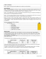
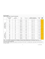
SciCan HYDRIM G4 Скачать руководство пользователя страница 6

SD-438 EU EN R5 

Electrical supply 
Refer to model number for specific requirements


Model Number 

Ending 

Current  

(see note 1) 

Voltage 

Frequency 

Maximum power supply 

location for installation site 

Rated 

load 

!

/

"


-D01 

12A 

208-240 V 

60 Hz 

1.50 m / 5 ft 

2.7 kW 


-D06 

12A 

200-230 V 

60 Hz 

1.50 m / 5 ft 

2.7 kW 


-D11 

12A 

200-230 V 

60 Hz 

1.50 m / 5 ft 

2.7 kW 


-D02 

12A 

200-230 V 

50 Hz 

1.50 m / 5 ft 

2.7 kW 


-D04 

12A 

200-230 V 

50 Hz 

1.50 m / 5 ft 

2.7 kW 


-D05 

12A 

200-230 V 

50 Hz 

1.50 m / 5 ft 

2.7 kW 


-D12 

12A 

200-230 V 

50 Hz 

1.50 m / 5 ft 

2.7 kW 


HYDRI

M

 C61wd 

G4


(in

clu

din

g L

C

S

 m

od

els)


-D13 

12A 

200-230 V 

50 Hz 

1.50 m / 5 ft 

2.7 kW 


-D01 

12A 

230-240 V 

60 Hz 

1.50 m / 5 ft 

2.5 kW 


-D03 

13A 

230-240 V 

60 Hz 

1.50 m / 5 ft 

2.5 kW 


-D02 

13A 

230-240 V 

50 Hz 

1.50 m / 5 ft 

2.5 kW 


-D04 

13A 

230-240 V 

50 Hz 

1.50 m / 5 ft 

2.5 kW 


HYDRI

M

 M

G4


(in

clu

din

g sh

ort m

od

els)


-D10 

13A 

230-240 V 

50 Hz 

1.50 m / 5 ft 

2.5 kW 


Note 1 - The HYDR

IM

 G4 is supplied with a domestic fused plug as standard. A dedicated hard wired supply can also be used. 

Note 2 - Due to the power requirements of the HYDR

IM

, (see rated load) especially during drying, it is advised that no other equipment is 

connected to the same supply outlet. 
Note 3 - Power supply outlet should be adjacent to the machine and NOT behind it. The cable should be routed away from the back panel and 
hot water inlet hose. 

Содержание HYDRIM G4

Страница 1: ...oes not compromise the function of the unit in any way Prior to installation it is important that the site be inspected and all the appropriate conditions are met to ensure the safe and efficient oper...

Страница 2: ...ounter it is recommended to allow at least 10 mm space at the top and both sides of the unit This will facilitate installation levelling and service access to the HYDRIM Note 2 Avoid installing the HY...

Страница 3: ...cold water feed valve so that both machine pipes can be connected to the cold supply The machine will not work with only one supply attached as it requires pressure in both supplies to activate the f...

Страница 4: ...o Sealed edges o Heat resistance o Sound structural integrity o Post installation access o Flatness See note 3 above Water Quality The quality of the water being used in the HYDRIM to clean the medica...

Страница 5: ...ort Note 1 The port should be installed in a cabinet adjacent to the unit Note 2 Ensure that the port has access to the office network and the internet Note 3 Although the unit can be connected to a b...

Страница 6: ...ls D13 12A 200 230 V 50 Hz 1 50 m 5 ft 2 7 kW D01 12A 230 240 V 60 Hz 1 50 m 5 ft 2 5 kW D03 13A 230 240 V 60 Hz 1 50 m 5 ft 2 5 kW D02 13A 230 240 V 50 Hz 1 50 m 5 ft 2 5 kW D04 13A 230 240 V 50 Hz 1...

Страница 7: ...feeds are installed Drain pipes are prepared Electrical requirements are met Cabinetry floors can withstand operation of the unit Water quality is acceptable Internet connection installed HIP HIP Ult...

Страница 8: ...for drying Total water consumption per cycle with drying P1 P2 11 4 L 1 5 L P3 30 3 L 2 5 L Maximum heat transmitted through fascia 1200 W Water softener salt capacity 0 5 kg 1 1 lbs Equipment instal...

Страница 9: ...nge 6 8 and 8 5 Water volume per process stage 8 L 1 L P3 has additional 8 1L for drying Total water consumption per cycle with drying P1 16 L 2 L P2 32 L 4 L P3 40 L 5 L Maximum heat transmitted thro...

Отзывы: