EASY-MAG-Series | Version 2.01
17
Operation
- When selecting protective gas bottles, it should be
borne in mind that over-sized bottles can impair the fle-
xibility and stability of the welding system and cause it
to tip over. In order to avoid damage to the device or
the dangers arising from the gas cylinder, only appro-
priate bottle sizes should be used. We therefore re-
commend bottle sizes up to a maximum of 20 liters. At-
tach the bottle with straps.
- After removing the protective cap, briefly open the cylin-
der valve in a direction away from the body to remove
any impurities. Screw pressure reducer to the threaded
connection of the protective gas cylinder. Make a hose
connection between the pressure reducer and the gas
supply connection at the top left of the back of the unit.
Secure the gas hose to the unit using the union nut and
the hose clamp on the pressure reducer. Then check
the tightness of the connections.
- Screw the pressure reducer (*) to the valve of the gas
cylinder. If argon gas or a mixture of argon and CO2 is
used, insert a special reducer in between which is
available as an accessory.
- Connect the gas supply hose to the reducer and tigh-
ten the supplied hose clamp.
- Loosen the adjusting nut of the pressure reducer be-
fore opening the cylinder valve.
(*
) The accessory must be purchased separately if it is not included with
the product.
9.4 Welding parameters
To obtain optimum welding results, the welding parame-
ters, such as the welding tension and wire feed speed,
must be adjusted according to the welding task, welding
position, material type and thickness. For every welding
wire diameter and every welding task optimal parame-
ters can be found. Among other things, they are recogni-
zable by the typical buzzing arc noise. If one deviates too
much from the optimal values, perfect welding is not pos-
sible.
Setting the welding parameters
After switching on the device, it is possible to start adju-
sting. First of all, the welding voltage is selected via the
STAGE SWITCH according to material thickness and
joint shape, then the wire feed speed is adjusted. For
coarse adjustment of the wire feed, the DRAHTVOR
PUSH BUTTON is moved to the middle position (level 5).
The settings should first be tested on a specimen. If the
welding result is not satisfactory, the wire feed can be
readjusted to plus or minus. It should be noted that the
wire feed is adjusted to each switching stage at the ope-
rating point setting. Using wire feed and welding voltage,
you can set the arc individually according to the applica-
tion.
Using the ratio voltage to current or voltage to wire feed
speed I can reach different arc lengths, which are used
for different applications. The main three types are exp-
lained later in this guide.
Setting aid:
The new adjustment aid makes it easier for the welder to
adjust the welding device. When selecting wire feed
speed level 5, the wire speed does not have to be cor-
rected for changes in the voltage levels (= welding cur-
rent), or only to a limited extent, since the device auto-
matically sets the optimum wire feed speed.
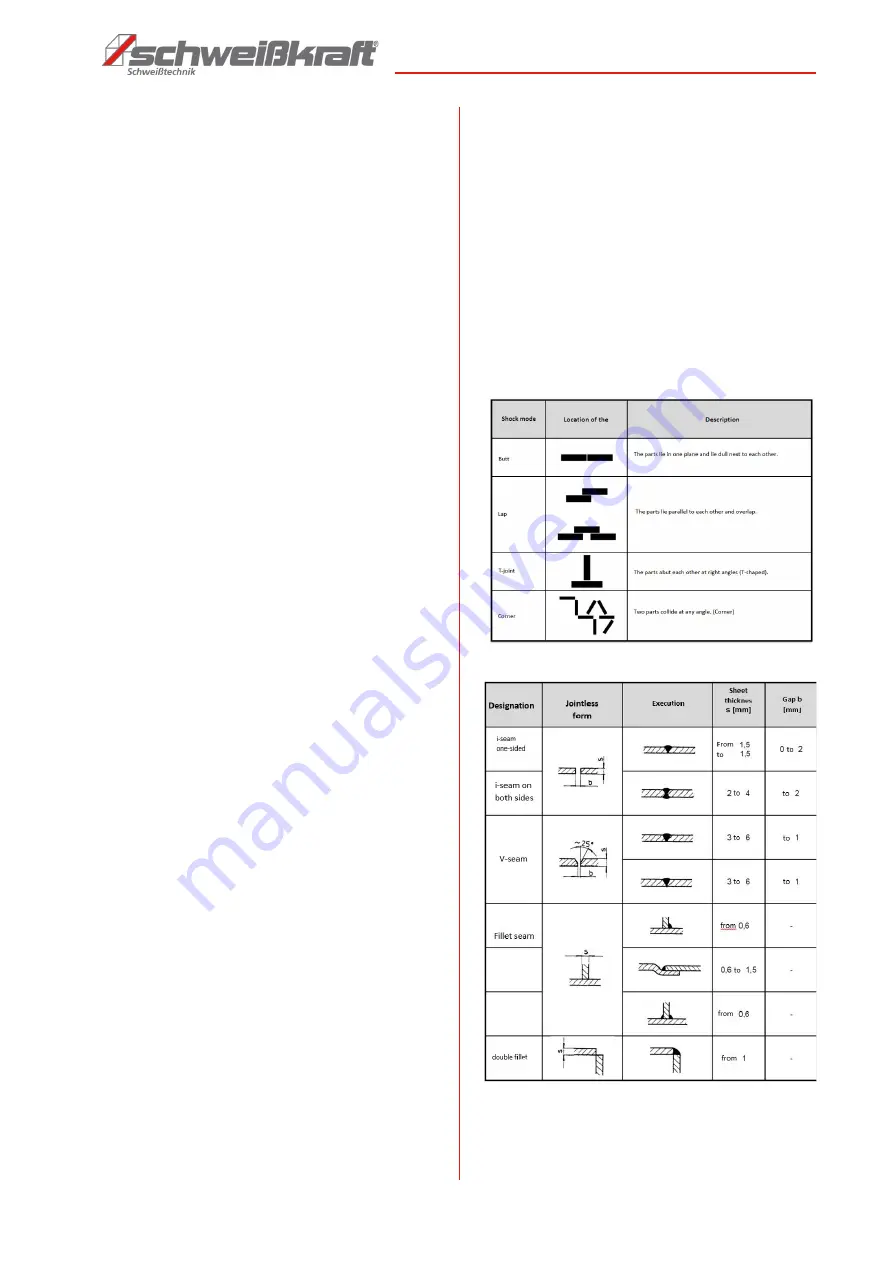
9.5 Preparation of the weld
The weld joint describes the weld and the special posi-
tion of the welded parts to each other. A particular type of
joint requires a corresponding seam type, which is also
determined by the sheet thickness, the seam preparation
(joint shape), the material and the welding process.
Groove shapes
The workpieces to be welded should be free of color, me-
tallic coatings, dirt, rust, grease and moisture in the seam
area. The welding preparation is to be carried out in accor-
dance with the welding regulations dseam planning.
Double fillet
weld
Содержание EASY-MAG 171
Страница 30: ...www schweißkraft de ...


