


6
Montage- und Betriebsanleitung für
Winkelgreifer Type SWG
Assembly and Operating Manual for
Angular Gripper Type SWG
Achtung!
Magnetfelder und magnetisierbare Stoffe können die
Näherungsschalter-Abfrage stören.
Zur Befestigung des Greifers nur Schrauben aus VA-
Material verwenden (nicht magnetisierbare Schrau-
ben). Befestigungsplatten, Halte winkel, usw. dürfen
nur aus nicht magne tisierbaren Werkstoffen, z.B. Alu
oder Kunststoff, bestehen.
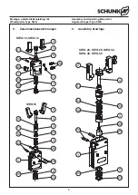
6.
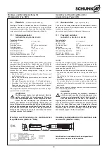
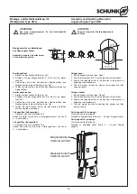
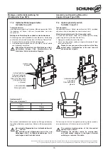
Luftanschluss
(Siehe Abbildung 2)
Achtung!
Bei der Montage des Greifers muss die Energie-
versorgung abgeschaltet sein. Beachten Sie auch die
Sicherheits hinweise auf den Seiten 3 und 4.
HINWEIS:
– Öffnen Sie nur die benötigten Anschlüsse und verschließen Sie
nicht benötigte Luftzuführungen mit geeigneten Blind stopfen.
– Für die schlauchlose Montage werden die O-Ringe aus dem
Beipack verwendet.
–
Druckmittel: Druckluft
Anforderung an die Druckluftqualität nach ISO 8573-1: 6 4 4.
7.
Problemanalyse
Der Greifer bewegt sich nicht:
– Luftversorgung überprüfen
– Mindestdruck unterschritten
– Luftleitungen vertauscht
– Näherungsschalter defekt oder falsch eingestellt
– Nicht benötigte Luftanschlüsse nicht verschlossen
– Bruch (Überlastung) der Kolbenstange
– Überprüfen, ob die Adapterplatte abgesetzt ist
(nur bei seitlicher Befestigung)
Der Greifer macht nicht den vollen Hub:
– Schmutz zwischen den Fingern und dem Gehäuse
– Mindestdruck unterschritten
– Magnet hat sich vom Kolben gelöst
Die Greifkraft lässt nach:
– Dichtungen überprüfen
– Greifer reinigen und neu schmieren
– Luftversorgung überprüfen
Der Greifer öffnet oder schließt stoßartig:
– Greifer reinigen und neu schmieren
Magnetschalter funktioniert nicht:
– Stahlschrauben zur Befestigung des Greifers verwendet
(VA-Schrauben verwenden)
– Befestigungsplatten, Haltewinkel usw. aus magnetisierbaren
Werkstoffen
(eventuell Alu oder Kunststoff verwenden)
cAutIOn!
Magnetic fields and magnetisable materials can
disturb the monitoring by proximity switches.
Only use screws made of stainless steel for fastening
the grippers (non-magnetisable screws). Fastening
plates, fixing brackets etc. should not be made out
of non-magnetisable materials such as aluminium or
plastics.
6.
Air connection
(See Illustration 2)
cAutIOn!
Before starting assembly of the gripper, the power
supply must be switched off. Please also consider
the safety hints on page 3 and 4.
NOTE:
– Open only the required connections and close off air intakes
that are not required with suitable dummy stoppers..
– The O-rings from the accessory bag are used for hose-free
assembly.
–
Pressure medium: compressed air
Standard for quality of the compressed air according to ISO
8573-1: 6 4 4.
7.
Trouble shooting
The gripper does not move:
– Check the air supply
– Pressure has dropped below minimum level
– Air lines incorrectly connected
– Proximity switch faulty or incorrectly set
– Unneeded connections not sealed
– Piston rod snapped (overload)
– Please check, if the adapter plate has a step on the side
(only when mounting it from the side)
The gripper does not complete the stroke:
– Dirt between the fingers and the housing
– Pressure has dropped below minimum level
– Magnet has disengaged from piston
Reduced gripping force:
– Check seals
– Clean and re-lubricate gripper
– Check the air supply
The gripper action is jerky when opening and closing:
– Clean and re-lubricate gripper
The magnetic switch does not function:
– Use screws made of stainless steel for fastening the grippers
– Fastening plates, fixing brackets etc. made of magnetisable
materials
(Maybe use aluminium or plastics)


