


13
Montage- und Betriebsanleitung für
Winkelgreifer Type SWG
Assembly and Operating Manual for
Angular Gripper Type SWG
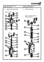
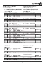
11. Zubehör
(auf besondere Bestellung)
Benötigen Sie mehr Informationen über die Handhabung von
Sensoren, wenden Sie sich vertrauensvoll an Ihren SCHUNK-
Ansprechpartner oder nutzen Sie unsere Download-Möglichkeiten
unter
www.schunk.com>Produkte>Automation>Zubehör
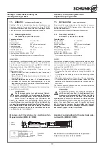
11.1 Näherungsschalter
für SWG 16, 20, 25, 32, 40, 50
Technische Daten:
Spannung:
10 – 30 V DC
Restwelligkeit:
≤
15%
Schaltstrom max.:
200 mA, kurzschlussfest
Schalthysterese:
0.8 mT
Temperaturbereich:
– 10°C bis + 70°C
Schaltfrequenz max.:
1000 Hz
Spannungsabfall ca.:
1.5 V
Schutzart nach DIN EN 60529: IP 67*
* für die Rundsteckverbindung nur im verschraubten Zustand
HINWEIS:
Die Näherungs- und Magnetschalter sind Zubehör und müssen
gesondert bestellt werden. Die Greifer sind von SCHUNK für
den Einsatz von Mag netschaltern der Type MMS 22 / RMS und
Näherungsschalter der Type INW 80/S vorbereitet.
Achten Sie auf einen sachgemäßen Umgang mit den
Näherungsschaltern:
– Ziehen Sie nicht am Kabel und lassen Sie den Sensor nicht
am Kabel baumeln.
– Ziehen Sie die Befestigungsschraube oder -klemmen nicht
übermäßig fest an.
– Zulässiger Biegeradius des Kabels = 15 x Kabel durchmesser.
– Vermeiden Sie Kontakt der Näherungsschalter zu harten
Ge genständen, sowie zu Chemikalien, insbe sondere Salpeter-,
Chrom- und Schwefelsäure.
Die eingesetzten induktiven Näherungsschalter sind ver polungs-
geschützt und kurzschlussfest.
Achtung!
Die Näherungsschalter sind elektronische Bau teile,
welche empfindlich auf hochfre quente Störungen
oder elektromagnetische Felder reagieren können.
Prüfen Sie die Anbringung und Installation des
Kabels. Der Abstand zu hochfrequenten Störquellen und
deren Zuleitung muss ausreichend sein. Das Parallelschalten
mehrerer Sensorausgänge der gleichen Bauart (npn, pnp) ist
zwar erlaubt, erhöht aber nicht den zulässigen Laststrom.
Beachten Sie weiterhin, dass sich der Leckstrom der einzel-
nen Sensoren (ca. 2 mA) addiert.
11. Accessories
(upon separate order)
If you would like more information on the operation of sensors,
please contact your SCHUNK representative. Information is also
available for download at
www.schunk.com>Products>Automation>Accessories
11.1 Proximity switches
for SWG 16, 20, 25, 32, 40, 50
Technical data:
Supply voltage:
10 – 30 V DC
Residual ripple:
≤
15%
Max. load current:
200 mA, short-circuit-proof
Hysteresis:
0.8 mT
Range of operating temp.:
– 10°C ... + 70°C
Max. operating frequency:
1000 Hz
Voltage drop, approx.:
1.5 V
Protect. class DIN EN 60529: IP 67*
* For concentric plug and socket only if assembled
NOTE:
Proximity and soleniod switches are accessories and have to be
ordered separately. The SCHUNK grippers are designed for the
use of soleniod switches of the type MMS 22 / RMS and proximity
switches of the type INW 80/S.
Make sure that the proximity switches are handled properly:
– Do not pull on the cable and do not swing the switch by its
cable.
– Do not tighten the fastening screw or the anchoring clip too
strongly.
– Admissible bending radius of the cable = 15 x cable diameter.
– Do not allow the proximity switch to make contact with hard
objects or with chemicals, especially nitric, chromic and sul-
phuric acid.
The inductive proximity switches used are short-circuit-proof and
have reverse voltage protection.
cAutIOn!
The proximity switches are electronic com ponents
which can react sensitively to high-frequency inter-
ference or electromagnetic fields. Check the attach-
ment and installation of the cable. The distance to
high-frequency sources of interference and their feed lines
must be sufficiently great. Connecting several sensor out-
puts of the same type (npn, pnp) in parallel is allowed,
but this does not increase the permissible load current.
Moreover, please note that the leakage current of the indivi-
dual sensors (approx. 2 mA) is cumulative.
Schaltfunktion: in unbedämpftem Zustand gezeichnet
Output: drawn in non-actuated condition
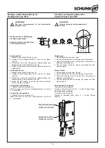
Montage und Einstellung der elektronischen
Magnetschalter (MMS 22 / RMS)
Assembly and adjustment of the electronic sole-
noid switch (MMS 22 / RMS)
ca. 300
22
M2
3.1
3.9
39.2
M8
x1
Ø 9.5
2 Stück
2 pieces


