Maintenance
02.00|1416054_ROTA-M2 + 2 |en-US
51
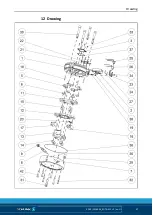
29 Place the mounting assembly on the chuck body assembly.
Observe the following points:
30 Thread the shaft of the mount into the drive rings
31 Thread the pin of the slide in the mounting assembly into the
sliding block of the chuck body assembly
32 Thread the slide of the chuck body assembly into the groove
of the mounting assembly
33 Fasten the mount (item 7) to the chuck body with screws
(items 31, 32 and 42)
34 Turn over the lathe chuck
35 Loosen screws (item 34) and fix the cover plate (items 23 and
24) against the mount (item 7), tighten the screws (item 34)
→ from size 800:
36 Fasten the mount (item 7) to the chuck body (item 1) with
screws (item 30)
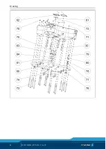
37 Fasten centering disk (item 63) with screw (item 75) to the
base plate (item 60)
38 Place the assembled base plate (item 60) on the mount (item
7). Carry out centering via the centering disk (item 63) and
alignment via the T-nut (item 80)
39 Screw in screw (item 73) and (item 74) into the base plate
(item 60)
40 Place the centering pin (item 64) in the center hole of the base
plate (item 60) and fasten with screws (item 81)
NOTICE
When assembling the base jaws and wedge bars, make sure that
the numbers on the base jaws and wedge bars match the
numbers on the jaw guidances.
Содержание ROTA-M flex 2+2 1000
Страница 20: ...Screw tightening torques 20 02 00 1416054_ROTA M2 2 en US Dimensions 3 2 ...
Страница 21: ...Screw tightening torques 02 00 1416054_ROTA M2 2 en US 21 ...
Страница 57: ...Drawing 02 00 1416054_ROTA M2 2 en US 57 Drawing 12 ...
Страница 58: ...Drawing 58 02 00 1416054_ROTA M2 2 en US ...


