


7
Montage- und Betriebsanleitung für
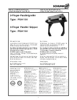
2-Finger-Parallelgreifer Type PGH 150
Assembly and Operating Manual for
2-Finger Parallel Gripper Type PGH 150
– During every maintenance lubricate rack, pinion and the run-
ning surfaces of the piston with Molykote BR 2 plus, Metaflux
Gleitmetall or a similar lubricating grease.
– All seals and sliding surfaces of the seals have to be lubri-
cated with Renolit HLT 2 or a similar grease. The seal kit is
available at SCHUNK.
Abschmierintervalle der Linearlager
PGH 150
halbjährlich
– Lubricate the linear bearings, using a high quality grease
basing on lithium (e.g. Multemp PS 2, Fuchs Renolit HP or
a similar grease with low viscosity to maintain the smooth
running of the bearing). The bearings have to be greased at
operating state temperature.
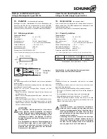
For greasing the linear bearings, the gripper finges, the base
jaws and the bellows have to be removed (See illustration on
page 8).
Apply the grease directly on the path of the linear guidance.
For an even distribution of the grease, please actuate the
gripper several times and if necessary, grease it again.
CAUTioN!
Never grasp into the open mechanics when the
gripper is actuated.
RiSK oF iNJURY!
– After lubrication, please assemble the bellow, base jaws and
gripper fingers again.
Environmental temperatures of more than 60°C / 140°F can
harden the used lubricants faster. Therefore, lubrication and
maintenance works have to be carried out more often.
9.
Disassembly of the gripper
(For item-nos. see Illustr. on page 8)
1. Remove the air connections.
2. Remove the screws (Item 30, 4 pcs. each) on side [
A] and [B]
and take off the covers (Item 11).
3. Remove the screws (Item 25, 2 pcs. each) on side [
A] and [B]
and take off the covers (Item 10).
4. Remove the seals as per the seal kit list (see chapter 9.1).
5. Thoroughly clean all components and check them on dam-
mage and wear-out.
6. Exchange all seals as per seal kit list (see chapter 9.1).
7. Before assembly, all seals and sealing faces has to be lubri-
fied (see chapter 8.1).
8. Assembly is done in reverse order.
Plug in the air connections at the sides
[A] and [B] and move the
gripper into the contrary postion.
Now steps 1 – 8 have to be carried out for the sides
[C] and
[D].
PGH 150
every 6 months
– Bei jeder Wartung die Kolbenlaufflächen, das Ritzel und die
Zahnstange am Kolben mit Molykote BR 2plus, Metaflux Gleit-
metall oder einem gleichwertigen Schmierstoff schmieren.
Die Dichtungen und alle Gleitflächen der Dichtungen mit
Renolit HLT 2 oder einem gleichwertigen Fett einschmieren.
Der Dichtsatz ist bei SCHUNK erhältlich.
Abschmierintervalle der Linearlager
– Die Linearlager mit einem hochwertigen Fett auf Lithiumbasis
abschmieren (z.B. Multemp PS 2, Fuchs Renolit HP oder
ein gleichwertiges Fett mit geringer Viskosität um die Leicht-
gängigkeit des Lagers zu erhalten). Die Lager in betriebs-
warmem Zustand ab schmieren.
Um die Linearlager abzuschmieren, müssen die Greiferfinger,
die Grundbacken und der Faltenbalg entfernt werden (siehe
Abb. auf Seite 8).
Das Fett direkt auf die Laufbahn des Führungs wagens auf-
tragen. Zur gleichmäßigen Verteilung des Fettes den Greifer
mehrmals betätigen und gegebenfalls nachschmieren.
ACHTUNG!
Beim Betätigen des Greifers nicht in die offene
Mechanik greifen.
VERLETZUNGSGEFAHR!
– Nach dem Abschmieren wieder den Faltenbalg, die Grund-
backen und die Greiferfinger montieren.
Umgebungstemperaturen über 60°C führen zu schnellerem Aus-
härten der eingesetzten Schmierstoffe. Schmier- und Wartungs-
arbeiten dementsprechend häufiger durchführen.
9.
Zerlegen des Greifers
(Pos.-Nummern siehe Abb. auf Seite 8)
1. Die Luftanschlüsse entfernen.
2. Die Schrauben (Pos. 30, je 4 St.) an den Seiten
[A] und [B]
entfernen und die Abdeckungen (Pos. 11) abnehmen.
3. Die Schrauben (Pos. 25, je 2 St.) an
[A] und [B] lösen und die
Abdeckung (Pos. 10) entfernen.
4. Alle Dichtungen gemäß Dichtsatzliste entfernen (siehe Kapitel
9.1).
5. Alle Teile gründlich reinigen und auf Defekte und Verschleiß
kontrollieren.
6. Alle Dichtungen gemäß Dichtsatzliste erneuern (siehe Kapitel
9.1).
7. Vor dem Zusammenbau alle Dichtungen und Dichtflächen
einfetten (siehe Kapitel 8.1).
8. Der Zusammenbau erfolgt in umgekehrter Reihenfolge.
Die Luftanschlüsse an den Seiten
[A] und [B] anschließen und
den Greifer in die entgegengesetzte Position fahren.
Jetzt die Schritte von 1. bis 8. für die Seiten
[C] und [D] durch-
führen.


