_________________________________________________________________________________________
schunk.com
XND.00005.022_A – 10/2018
31
3.1.4
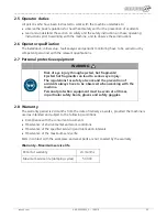
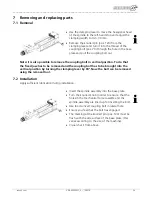
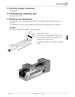
Removing the spindle assembly
Use the clamping lever to move the hexagonal head
of the spindle to the left-hand stop and adjust the
clamping width to min. 30 mm.
Remove the knurled pin (pos. 120) from the
clamping lever and turn it into the thread of the
couplimng bolt (pos. 70) through the hole in the
base plate and pull the coupling bolt out.
The spindle assembly can now be pulled out for
cleaning or releasing the base plate.
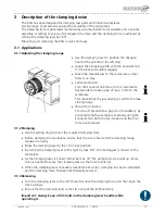
Note: it is also possible to remove the coupling bolt in vertical position. To do that
the fixed jaw has to be removed and the coupling bolt has to be brought into the
vertical position by turning the clamping lever to the right by 90°. After that you can
remove the bolt using the disassembly tool.
3.1.5
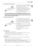
Fitting the spindle assembly
Insert the spindle assembly into the base plate.
Turn the knurled knob in order to ensure that the
holes in the mechanical force cassette and the
spindle assembly are lined up for inserting the bolt.
Use tool to insert coupling bolt in lateral hole.
Check whether the locking of the bolt in the pull
rod can be felt.
The marking at the knurled pin (pos. 120) must be
flush with the side surface of the base plate. (this
varies according to the size of the machine)
Visual check from above.
Remove the knurled pin and turn on to the
clamping lever.
3.1.6
Changing jaws
Release screws and remove the jaws.
Clean and oil the contact surfaces, e.g. with MOTOREX Supergliss 68 K to ISO VG 68.
Insert the jaws and tighten crosswise using original screws.
Use 60 Nm to tighten jaws of widths 100 and 125 and use 150 Nm for 160 jaws.
3.1.7
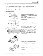
Cover sheets
Cover sheets are not mandatory because the spindle does not turn during the clamping
process.
A set of cover sheets is supplied for additional protection.
Select the appropriate sheet sizes suitable for the clamping range and engage in the V-groove
in the base plate or, with KSG 160, slide in from the rear and engage in the nut.
For larger clamping ranges it is possible to combine several sheets. The cover sheets can be
removed by gripping from below and pulling upwards or by removing the spindle assembly.

