


Maintenance
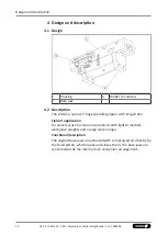
7.4 Disassembly and assembly
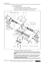
7.4.1 Disassembling
Position of the item numbers
1. Remove pressure lines.
2. Unscrew and remove the screws (35) and remove holder (21)
with the proximity switches.
3. Completely unscrew the air connections (43) with a suitable
wrench (open-ended or box wrench).
4. Remove the screws (40) and take off the cover (10).
5. Manually push the gripper fingers (3) all the way apart (open
gripper position).
6. Completely screw out the screws (33).
7. Carefully pull out the gripper fingers (3) to the side.
8. Pull the quad rings (24) off the piston (6).
9. Remove the O-rings (25) from the covers (7).
10. Turn the pistons (6) from the piston rod (2).
11. Pull the cover (7) from the piston rod (2).
12. Remove the quad rings (23) from the covers (7).
13. Release the set-screw (34) and screw out about 2 mm.
14. Remove the screws (38).
15. Pull the piston rod (2) carefully out of the housing (1).
IMPORTANT! Be sure that the pinion (20) and its associated
alignment pin (29) remain in their prescribed position.
16. Take the O-rings (26) out of the housing's (1) counterbores.
WARNING
Risk of injury due to unexpected movements!
If the power supply is switched on or residual energy remains in
the system, components can move unexpectedly and cause
serious injuries.
•
Before starting any work on the product: Switch off the power
supply and secure against restarting.
•
Make sure, that no residual energy remains in the system.
7.4.2 Assembling
•
Assembly takes place in the opposite order to disassembly.
Observe the following: Unless otherwise specified, secure all
screws and nuts with Loctite no. 243 and tighten with the
appropriate tightening torque.
IMPORTANT! When inserting the gripper fingers (3) – with
guide (19) and gear rack (18) – be sure that both gear racks
(18) come together at the pinion (20) at the same time.
27
04.00 | KGG 220 - 280 | Assembly and Operating Manual | en | 389168


