


Assembly
01.00| |en
19
Assembly
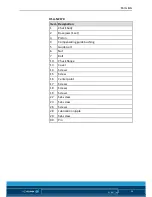
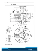
The specified item numbers for the corresponding individual
components relate to the enclosed drawings or to the Drawings
chapter
(
12, Page 30)
.
Pre-assembly measures
Carefully lift the product (e.g. using suitable lifting gear) from the
packaging.
CAUTION
Danger of injury due to sharp edges and rough or slippery
surfaces
Use personal protective gear, especially safety gloves.
Check the delivery for completeness and for transport damage.
Assembly of the HSA chuck
• Check the machine spindle nose and ready-machined inter-
mediate flange for radial and axial run-out. The permissible
limit is 0.005 mm in accordance with DIN 6386 and ISO 3089.
• The contact surface must be chamfered and completely clean
at the bore holes.
• Unscrew the cylindrical screws (Item 18) and remove the guide
bushing (Item 4, 11, or 13).
• Actuate the clamping cylinder to slide the draw tube to the
front position (see illustration: "Mounting the chuck")
HSA 160, 160/2, NZ 170/2, 180/2, 200, 250, 250/2, 265, 315,
315/2 and 400:
• Screw the intermediate flange (Item 10) onto the spindle using
the screws (Item 19).
• Move the guide part (Item 5) to the front position.
• Raise the chuck in front of the spindle lug using an assembly
belt or eye bolt until it is flush with the center of the spindle.
7
7.1
7.2


