background image


General 


02.00|ROTA NC plus 2 / ROTA NCF plus 2 |en 


General 

This operating manual is an integral component of the product and 
contains important information on safe and proper assembly, 
commissioning, operation, care, maintenance and disposal. This 
manual must be stored in the immediate vicinity of the product 
where it is accessible to all users at all times. 

Before using the product, read and comply with this manual, 

especially the chapter “Basic safety notes”.

(

 2, Page 7)


If the product is passed on to a third party, these instructions must 
also be passed on. 

Illustrations in this manual are provided for basic understanding of 
the product and may differ from the actual product design. 

We accept no liability for damage resulting from the failure to 
observe and comply with this operating manual.


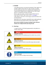
Warnings 

To make risks clear, the following signal words and symbols are 
used for safety notes. 


DANGER 

Danger for persons! 

Non-observance will inevitably cause irreversible injury or death. 


WARNING 

Dangers for persons! 

Non-observance can lead to irreversible injury and even death. 


CAUTION 

Dangers for persons! 

Non-observance can cause minor injuries. 


NOTICE 

Material damage! 

Information about avoiding material damage. 


1.1 

Содержание 0852106

Страница 1: ...Translation from the original operating manual Power chuck ROTA NC plus 2 ROTA NCF plus 2 Assembly and Operating Manual Superior Clamping and Gripping...

Страница 2: ...ions for the purpose of technical improvement Document number 0889127 en Version 02 00 17 06 2019 en H D SCHUNK GmbH Co All rights reserved Dear Customer thank you for trusting our products and our fa...

Страница 3: ...for clamping force and speed 21 6 3 1 Calculation of the required clamping force in case of a given rpm 22 6 3 2 Calculation example required initial clamping force for a given speed 24 6 3 3 Calcula...

Страница 4: ...2 en 8 3 Disassembly and assembly of the Chuck 36 9 Maintenance 38 9 1 Lubrication 38 9 2 Maintenance intervals 39 9 3 Changing the top jaws 39 10 Disposal 40 11 Spare parts 40 12 Drawing 42 13 Trans...

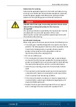
Страница 5: ...party these instructions must also be passed on Illustrations in this manual are provided for basic understanding of the product and may differ from the actual product design We accept no liability f...

Страница 6: ...CF plus 2 en WARNING Warning about hand injuries WARNING Warning about hot surfaces Applicable documents Technology chapter in the lathe chuck catalog The documents marked with an asterisk can be down...

Страница 7: ...ed use also means that the user has read and understood this operating manual in its entirety especially the chapter Basic safety notes The maximum RPM of the chuck and the required clamping force mus...

Страница 8: ...lathe chuck s clamping force until the machine comes to a standstill and the workpiece can be secured e g using a crane or suitable lifting equipment The machines and equipment must fulfill the minimu...

Страница 9: ...nd a hairnet when working on the machine and the lathe chuck WARNING Risk of injury due to dropping the chuck during transport installation or removal Take special care in the danger zone when transpo...

Страница 10: ...due to incorrect choice of clamping position for chuck jaws on workpiece If an incorrect clamping position is chosen for the chuck jaws on workpiece the base and the top jaws may be damaged The T nuts...

Страница 11: ...t max operating force pressure Stroke control The stroke of the clamping piston must allow a safety zone at the front and rear end position The machine spindle may only be started when the clamping pi...

Страница 12: ...mes lubricate again and then check the clamping force We recommend checking the clamping force using a clamping force tester before starting a new production run and between maintenance intervals Only...

Страница 13: ...e designed to be as light and as low as possible The clamping point must be as close as possible to the chuck face clamping points at a greater distance lead to greater surface pressure in the jaw gui...

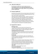
Страница 14: ...pervision of qualified specialists Organizational measures Obeying the rules Via suitable organizational measures and instructions the operator must ensure that the relevant safety rules are obeyed by...

Страница 15: ...NC plus 2 ROTA NCF plus 2 en 15 Using personal protective equipment When using this product you must comply with the relevant health and safety at work rules and you must use the required personal saf...

Страница 16: ...nting screws used to clamp the chuck on lathes or other suitable technical equipment screw quality 10 9 Screw size M6 M8 M10 M12 M14 M16 M18 M20 M22 M24 M27 M30 Admissible torque MA Nm 13 28 50 88 120...

Страница 17: ...C with centrifugal force compensation taken into account The specified maximum speed of rotation stated only applies when using the maximum clamping force and the SHB type hard standard stepped jaws...

Страница 18: ...he maximum actuating force was applied and the jaws were set flush with the outer diameter of the chuck The chuck is in perfect condition and lubricated with SCHUNK LINOMAX special grease If one or mo...

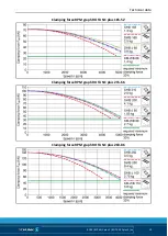
Страница 19: ...Technical data 02 00 ROTA NC plus 2 ROTA NCF plus 2 en 19 Clamping force RPM graph ROTA NC plus 185 52 Clamping force RPM graph ROTA NC plus 215 66 Clamping force RPM graph ROTA NC plus 260 86...

Страница 20: ...Technical data 20 02 00 ROTA NC plus 2 ROTA NCF plus 2 en Clamping force RPM graph ROTA NC plus 315 104 Clamping force RPM graph ROTA NC plus 185 52 Clamping force RPM graph ROTA NCF plus 215 66...

Страница 21: ...ugal force N McAB Centrifugal torque of top jaws Kgm Fsp Effective clamping force N McGB Centrifugal torque of base jaws Kgm Fspmin Minimum required clamping force N n Speed rpm Fsp0 Initial clamping...

Страница 22: ...ce Fc is the effective clamping force Fsp for gripping from the outside inwards for gripping from the inside outwards DANGER Risk to life and limb of the operating personnel and significant property d...

Страница 23: ...ing force Fsp and the total centrifugal force Fc is multiplied by the safety factor for the clamping force Ssp According to VDI 3106 the following also applies here Ssp 1 5 The total centrifugal force...

Страница 24: ...nmax 3200 rpm Chuck data table RPM n 1200 rpm application specific Mass of one top jaw mAB 5 33 kg application specific Center of gravity radius of top jaw rsAB 0 107 m application specific Safety fac...

Страница 25: ...ulate the permissible RPM for a given initial clamping force during shutdown NOTICE The calculated permissible RPM may not exceed the maximum RPM inscribed on the chuck for safety reasons Example of c...

Страница 26: ...RPM of the chuck nmax 3200 rpm see Chuck data table 6 1 Page 17 This calculated RPM may be used Grades of Accuracy The radial and axial runout tolerance correspond to the technical delivery specificat...

Страница 27: ...ponding individual components relate to chapter drawings 12 Page 42 Pre assembly measures Carefully lift the product e g using suitable lifting gear from the packaging CAUTION Danger of injury due to...

Страница 28: ...eck the mounting surfaces on the spindle for radial and axial run out with a dial indicator see Fig Assembly of the chuck A A maximum radial run out error of 0 005 mm on the centering mount and a maxi...

Страница 29: ...user himself must be finished machining on the machine spindle and must be balanced before the chuck is mounted After mounting it must be ensured that the flange is fitted tightly on the entire surfa...

Страница 30: ...nt with a through screw connection the flange is first attached to the chuck and subsequently mounted on the spindle Before mounting the chuck flange on the cylindrical recess of the chuck dirt and sw...

Страница 31: ...or chucks according to DIN ISO 3442 3 Mounting the ROTA NC plus NCF plus chuck with a centering edge Remove cylindrical screws of the top jaws together with the T nuts Item 46 Move the draw tube to th...

Страница 32: ...ernately Check radial and axial runout on the control edge 7 2 Page 28 Check the function and level of the actuating force Check the ease of movement and jaw stroke of the base jaws Mount the top jaws...

Страница 33: ...he draw tube to the chuck Adapter ROTA A B C D E F O ring NC plus 2 NCF plus 2 185 52 M67 x 1 5 15 0 52 65 2 4 58 66 x 2 NC plus NCF plus 315 104 M74 x 1 5 15 0 66 72 2 4 70 72 x 2 NC plus 2 NCF plus...

Страница 34: ...the large jaw stroke We recommend automatic loading If manual loading is used set up the jaw position so that there is no risk of injury when inserting the parts The maximum opening gap must be less...

Страница 35: ...jaws can be mounted and removed manually without any tools Position the chuck jaws as in Fig 1 and then slide into the hook until the chuck jaws noticeably engage The quick change shown is only suitab...

Страница 36: ...uck it must be removed 7 3 Page 29 Remove the screws Item 28 and use the press off threads to press off the center sleeve Item 4 from the chuck body Item 1 and then remove it entirely Mark the positio...

Страница 37: ...s available from SCHUNK CAUTION Allergic reactions due to grease in contact with skin Wear gloves Assemble the chuck in reverse order During assembly special care must be taken that the numbers of the...

Страница 38: ...be checked after a specific period of operation see Maintenance intervals chapter 9 2 Page 39 Only use a calibrated clamping force tester for measuring in the clamping force test SCHUNK SGT 270 Techni...

Страница 39: ...n Wear gloves Maintenance intervals Lubrication of the grease areas Lubrication interval Strain every 25 hours normal coolant utilization every 8 hours high coolant utilization after 1200 hours or as...

Страница 40: ...ernatively you can return the chuck to SCHUNK for proper disposal Spare parts When ordering spare parts it is imperative to specify the type size and above all the manufacturing no of the chuck Seals...

Страница 41: ...ession spring 2 27 Steel ball 2 28 Screws 3 29 Screws 6 30 Screws 3 31 O ring 1 33 Conical lubrication nipple 3 35 O ring 1 36 Support ring 1 37 O ring 1 38 O ring 1 39 Seal 3 41 Compression spring 6...

Страница 42: ...Drawing 42 02 00 ROTA NC plus 2 ROTA NCF plus 2 en Drawing Only for NCF plus 2 Only for chuck sizes 260 315 Only for NC plus 2 12...

Страница 43: ...ot be put into operation until conformity of the machine into which the incomplete machine is to be installed with the provisions of the Machinery Di rective 2006 42 EC is confirmed Applied harmonized...

Страница 44: ...relevant 1 1 Essential Requirements 1 1 1 Definitions X 1 1 2 Principles of safety integration X 1 1 3 Materials and products X 1 1 4 Lighting X 1 1 5 Design of machinery to facilitate its handling X...

Страница 45: ...1 6 5 Cleaning of internal parts X 1 7 Information 1 7 1 Information and warnings on the machinery X 1 7 1 1 Information and information devices X 1 7 1 2 Warning devices X 1 7 2 Warning of residual...

Отзывы: