Acuity AP820 Laser
Scanners Rev. 3.3
14
4.
Installation and Checkout
4.1
Mounting
The scanner should be securely mounted to rigid heat dissipating mechanical fixtures,
brackets or stages. In environments of high vibration, consider using insulating
bushings with a bracket to minimize the transfer of this movement to the scanner.
The floors of some industrial environments could transfer vibration to scanner fixtures
and care should be taken to eliminate this source of displacement measurement error.
Never weld the scanner in place and avoid using a welder’s arc on metal
fixtures with the scanner connected.
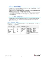
Consult the appropriate mechanical drawings (see section Mechanical Dimensions 3.2) to
locate the size and location of the mounting holes for each scanner model. For the
smaller models, the mounting holes are located on the side of the scanner head to
conserve space. The small enclosures have two mounting holes on the side of the sensor.
The medium enclosure models have three through holes that should be used for secure
mounting.
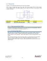
Sensors should be mounted perpendicular to the target surface that it will be measuring.
Mount the sensor at the appropriate height above the target surface. Consult the
product data sheet to determine the sensor’s standoff distance. It will only measure
distance between the Range Beginning and Range End.
4.2
Cabling
The AP820 sensors have two cable receptacles, one for Ethernet and one for Power /
Interface. The sensors can be ordered with cables of desired length, or users may
choose to manufacture their own cables.
4.2.1
Control cable
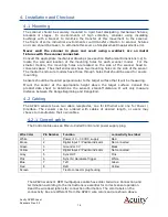
The Control cable uses an M12-A-Coded Control and power supply plug.
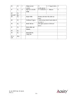
The AP820 scanner’s OEM multipurpose cable has solder tail wires. Connection and
termination according to the instructions is essential for correct sensor operation.
Read the wire descriptions for connection information. The color labels on the
connectivity box are different from the AP820 wire colors and are shown above.
Wire Color
Pin Number
Function
connectivity box label
White
1
Power +10
– 30 VDC, supply
Red
Brown
2
Digital Input 1 / Position indicator
Not connected
Green
3
Ground or 0 V
Black
Yellow
4
Digital Input 2 / Position indicator
Not connected
Gray
5
Sync OUT
Pink
Pink
6
Sync IN / Hardware Trigger
White
Blue
7
TxD
Green
Red
8
RxD
Yellow
Screen
Tied to connector plug housing


