Step 2 — Connect the System
Important:
When connecting Ultra-Lock cordsets to the
FIS
-
0
870
and
ZAA12NN01
, align the pins first and then push the connector into
place. Do not twist the connectors, as this will bend the pins.
Important:
Do not attempt to power more than four scanners with
a single power supply in a daisy chain configuration. Add a
ZAA12NN01 a
nd one power supply for every four additional
scanners in the d
aisy chain.
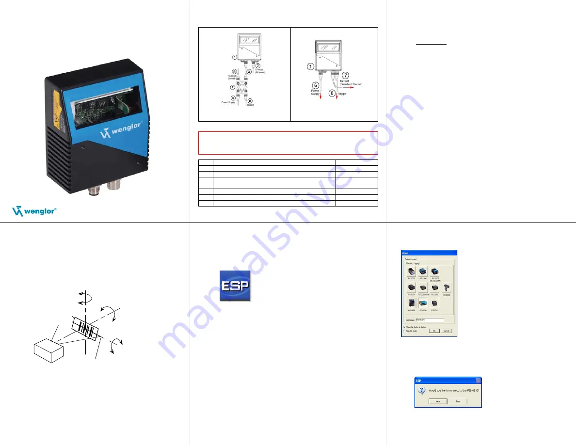
RS-232
1. Connect the Serial Communication Cable from “A” on the
FIS-0
870 to “2” on the
AB
-
0830
.
2. Connect the host cable from “1” on the QX-1 to the host computer.
3. Connect the photo sensor to “T” on the ZAA12NN01.
4. Connect the power supply to “3” on the ZAA12NN01.
5. Plug in the power supply.
Ethernet
1. Connect the Ethernet Cable from “B” on the
FIS
-
0
870 to the
network.
2. Connect the power supply to “A” on the
FIS
-
0
870.
3. Plug in the power supply.
Step 1 — Check Hardware
Item
Description
Part Number
1
FIS
-
0
870 Industrial Raster Scann
FIS-0870-XXXX
2
Interface Device
ZAA12NN01
3
Cordset, Common, M12 12-pin Plug to M12 12-pin Socket, 1 m
ZAV12Rx01
5
Cordset, Host, Serial, M12 12-pin Socket to DB9, 1 m
ZAV13Rx01
6
Power Supply, M12 12-pin Socket, 1.3 m
NT-10
7
Cordset, Host, Ethernet, M12 8-pin Plug to RJ45, 1 m
ZAV88Rx01
8
Photo Sensor, M12 4-pin Plug, NPN, Dark On, 2 m
Note:
Additional cordsets and accessories are available in the Microscan Product Pricing Catalog.
Caution:
Be sure that all connections are secure
BEFORE
applying power
to the system. Always power down
BEFORE
disconnecting any cables.
Hardware Required
Standalone (
ZLWK=$$11
)
Standalone (without
$$11
)
Quick Start Guide
FIS-0870 Industrial
Sweep Raster Scanner
P/N 83-110870 Rev B
Step 3 — Position Scanner
1. Place a test symbol in a location with as little ambient light
as possible.
2. Position the scanner at the focal distance used in your application.
3. Align the test symbol with the scanner’s field of view.
4. Tip the scanner relative to the test symbol to avoid glare
from specular reflection.
Pitch
axis
Bar code
label
Tilt
axis
axis
Scan line
Scanner
Pitch
Tilt
Skew
Symbol
Scanner
Maximum
skew, tilt,
and pitch:
±30°
Step 4 — Install ESP
ESP Software can be found on the
wenglor
Tools CD that is
packaged with the
FIS
-
0
870.
1. Follow the prompts to install ESP from the CD.
2. Click on the ESP icon to run the program.
Note:
ESP can also be installed from the
Download Center
at
Refer to the
F
,6
-
870 Industrial Raster Scanner User’s Manual
for
detailed information about using ESP to configure the
FIS
-
0
870.
Step 5 — Select Model
When you start ESP, the model menu will appear:
1. Click the button showing the
FIS
-
0
870.
2. Click
OK
.
Note:
You can also simply double-click the button showing
your scanner to make your selection.
3.
Click
Yes
when this dialog appears:
Note:
If you need to select another model later, click the
Switch Model
button near the top of the screen or use
Model > New Model
in the menu toolbar.